
Preston Cinema Systems · 1659 Eleventh Street · Santa Monica, CA 90404
tel 310-453-1852 fax 310-453-5672 www.prestoncinema.com
The Light Ranger 2 (LR2) provides groundbreaking enhancements to the art of focus pulling. Focus assist graphics are overlaid the camera image displayed on the video monitor. The graphics show the direction and amount the focus knob must be turned to bring subjects within the lens depth of field. This intuitive representation of focus allows an immediate response to changes in the camera to subject distance.
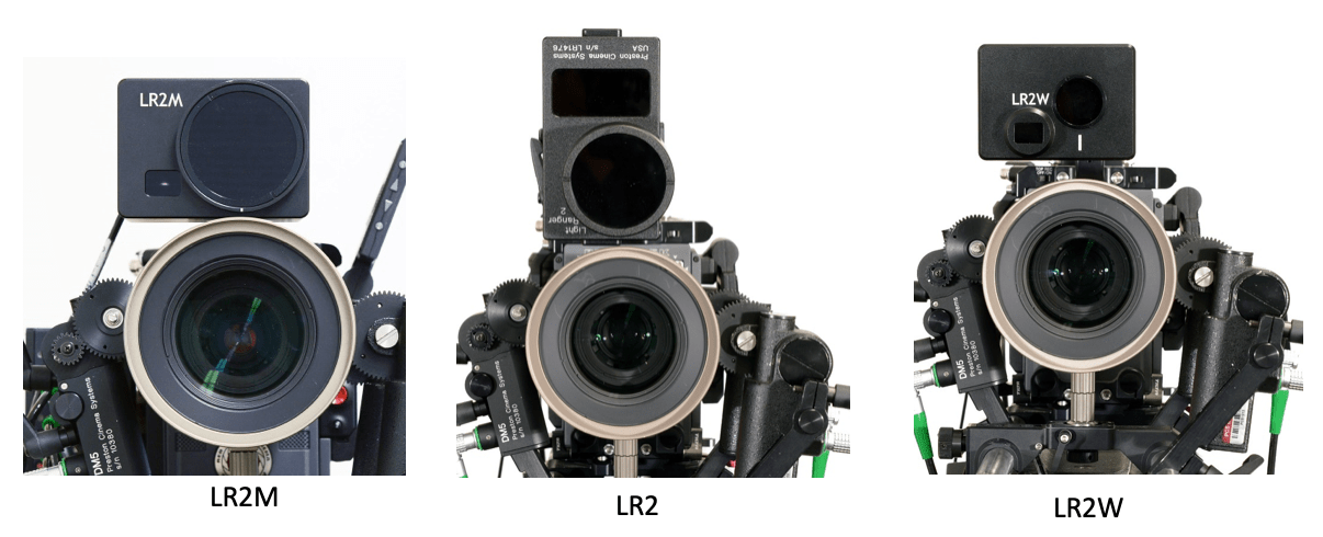
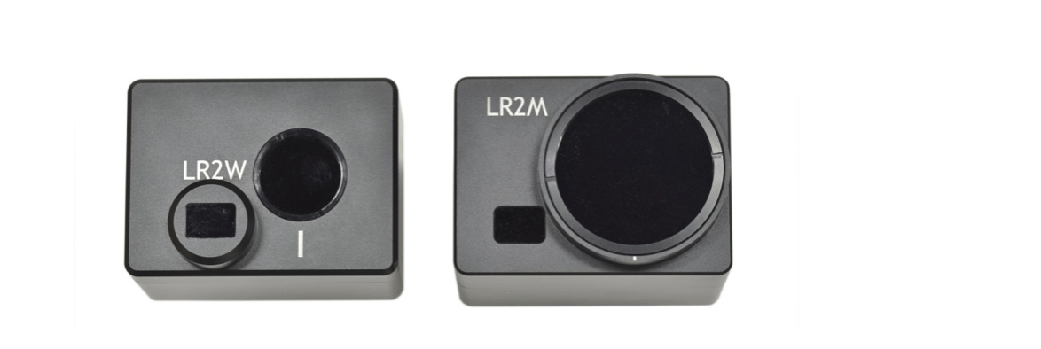
The LR2 system consists of one or more LR2 sensors and the Video Interface unit for generating overlay graphics. The LR2W and LR2M sensors are each optimized for use with wide angle and mid to long focal length lenses respectively.
Operating Principle
The LR2 sensors emit short pulses of infra-red light in a fan shaped beam from the small rectangular opening next to the lens.
The reflections from subjects illuminated by the beam are focused by the LR2 receiving lens (round opening) onto an array of sixteen detectors and timed to determine their distance from the LR2. The distance data from the sixteen detection areas is combined with the lens settings in the hand unit to form the focus assist graphics.
The maximum range depends on the size and reflectivity of the subject. The typical range to a person is 40’ (13m) or greater. The range is unaffected by ambient illumination and the LR2 will work both in bright sunlight or complete darkness.
A. LR2 Sensor Mounting to Camera
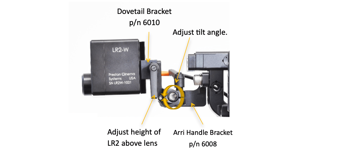
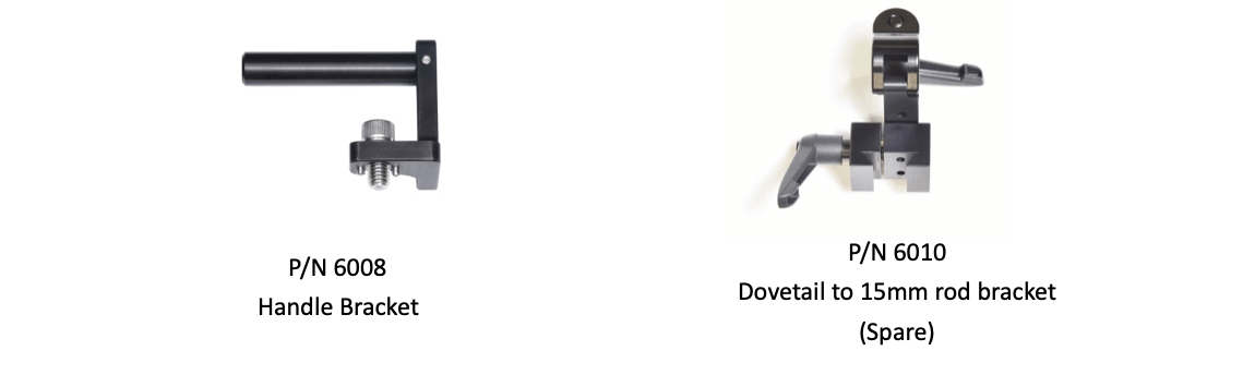
Mount the LR2 on the camera. The Arri Handle Bracket ( p/n 6008) shown below attaches to the handle with a 3/8-16 screw.
Loosen the handle on the Dovetail bracket. Slide the LR2 so that it clears the lens and matte box. Minimize parallax between the camera and LR2 by positioning the LR2 as close to the lens as possible. Center the LR2 receiver lens (round opening) horizontally over the camera lens (pictures below).
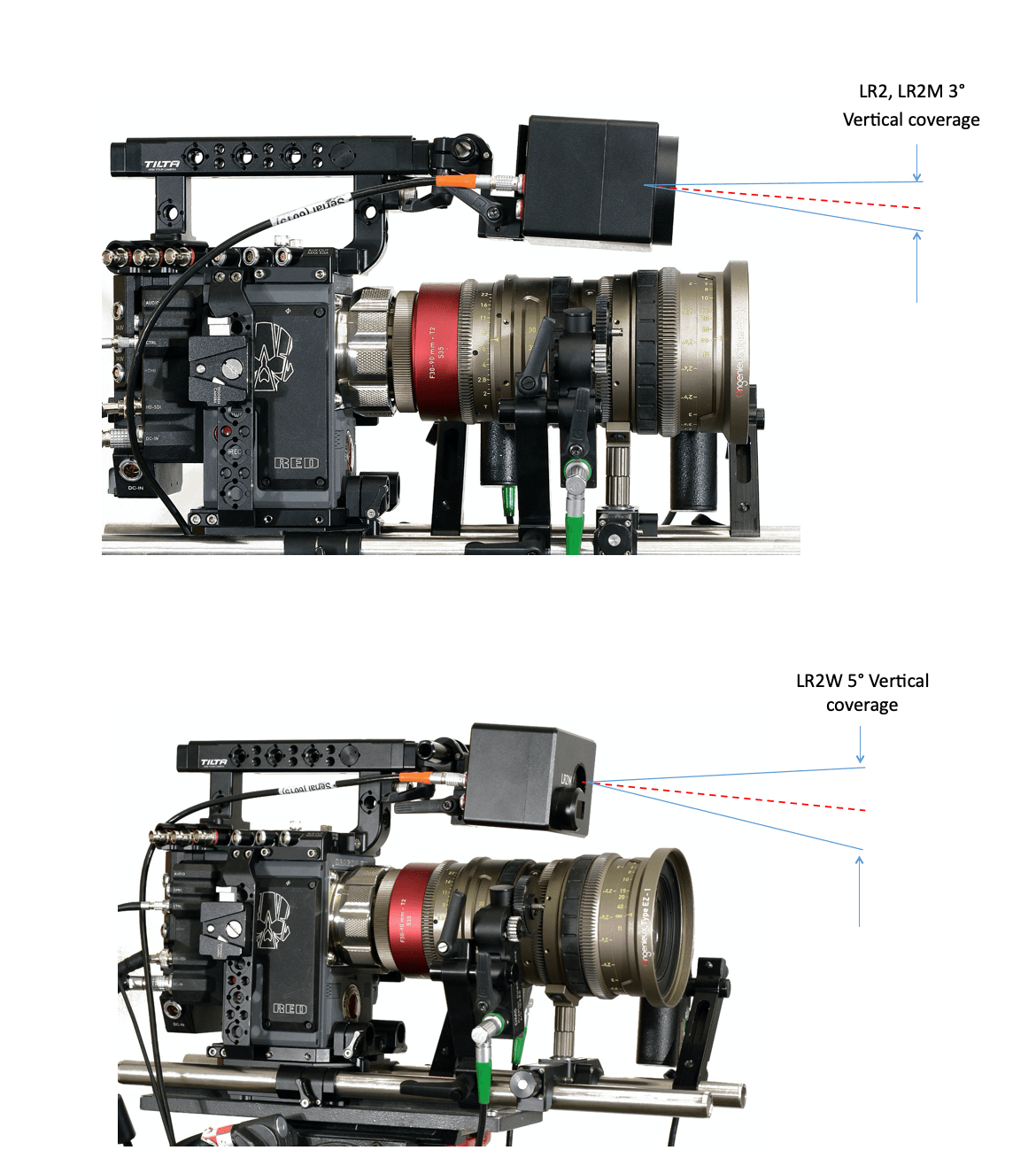
B. Tilt Angle
Adjust the tilt angle so that the Light Ranger can measure subject distance when the subject is at the closest distance to the camera. The LR2 and LR2M have 3° vertical coverage and the vertical coverage for the LR2W is 5°.
Tilt Angle Adjustment and Vertical Coverage LR2W and LR2M
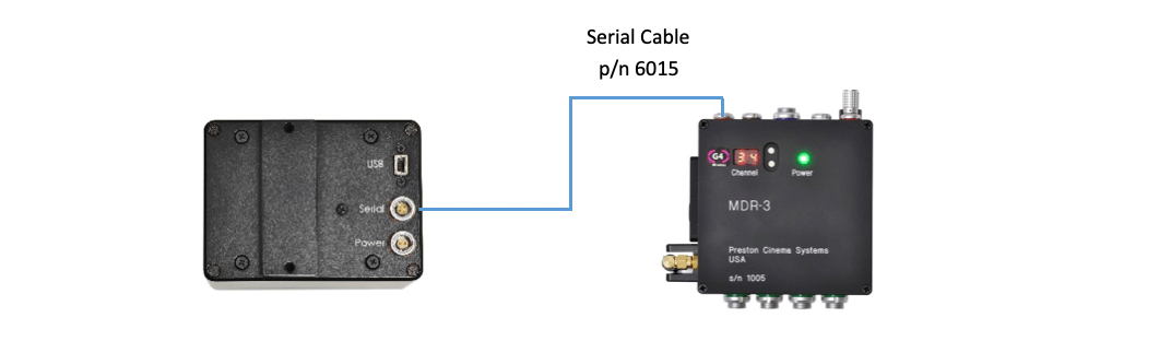
C. LR2 Cable Connections
(1) Connect the serial cable P/N 6015 from the LR2 to the Serial receptacle of the MDR3/4.
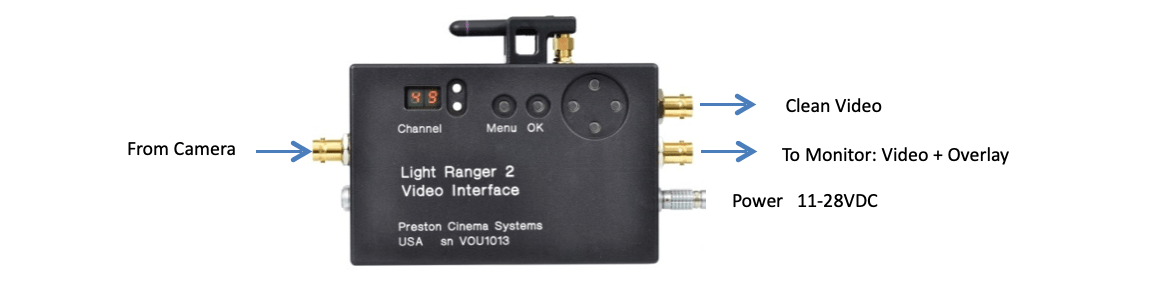
(2) Video Interface (VI) cables.
D. Set the camera monitor output to one of the supported video frame rates:
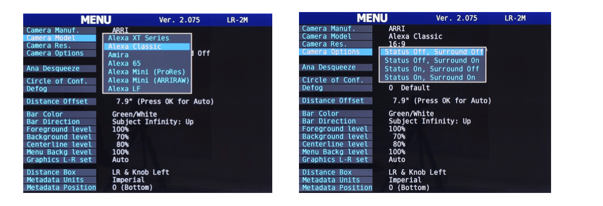
A. The first four menu items match the overlay graphics to the horizontal field of view of the camera. Select the camera options from the drop-down menus.
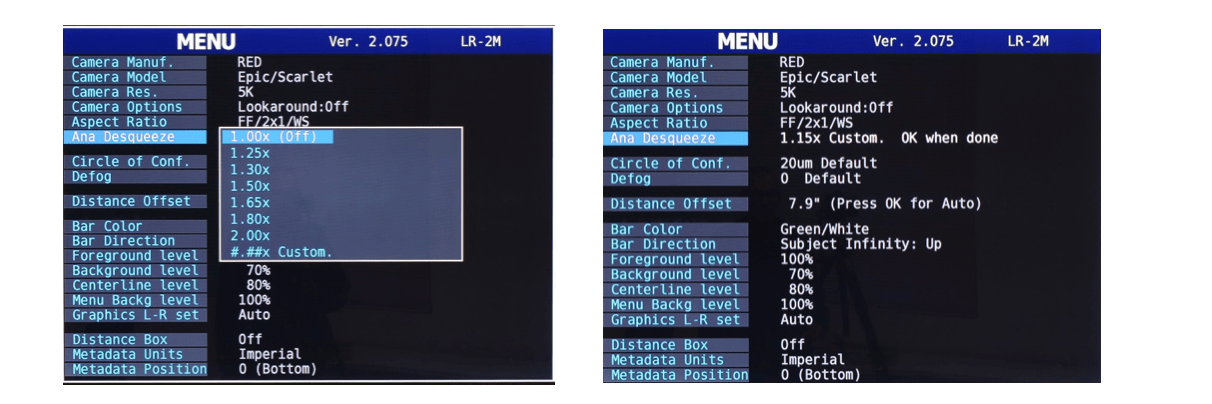
B. The Anamorphic Desqueeze scales the horizontal field of view according the lens de-squeeze factor. The Custom setting allows you to set squeeze values from 0.5 to 3.0.
To select a custom squeeze value, select “#.##* Custom”, and use the East/West switches on the Video Interface to increment/decrement the displayed value. Press ok on the VIU when done.
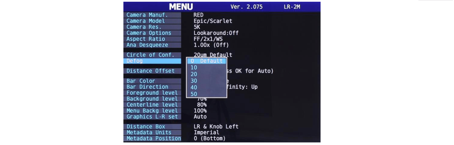
C. The Circle of Confusion (below) determines how the lens depth of field is calculated from the lens T-stop and focal length. The display of the green bars indicating whether the subject is within the DOF will be shown in accordance with the Circle of Confusion.
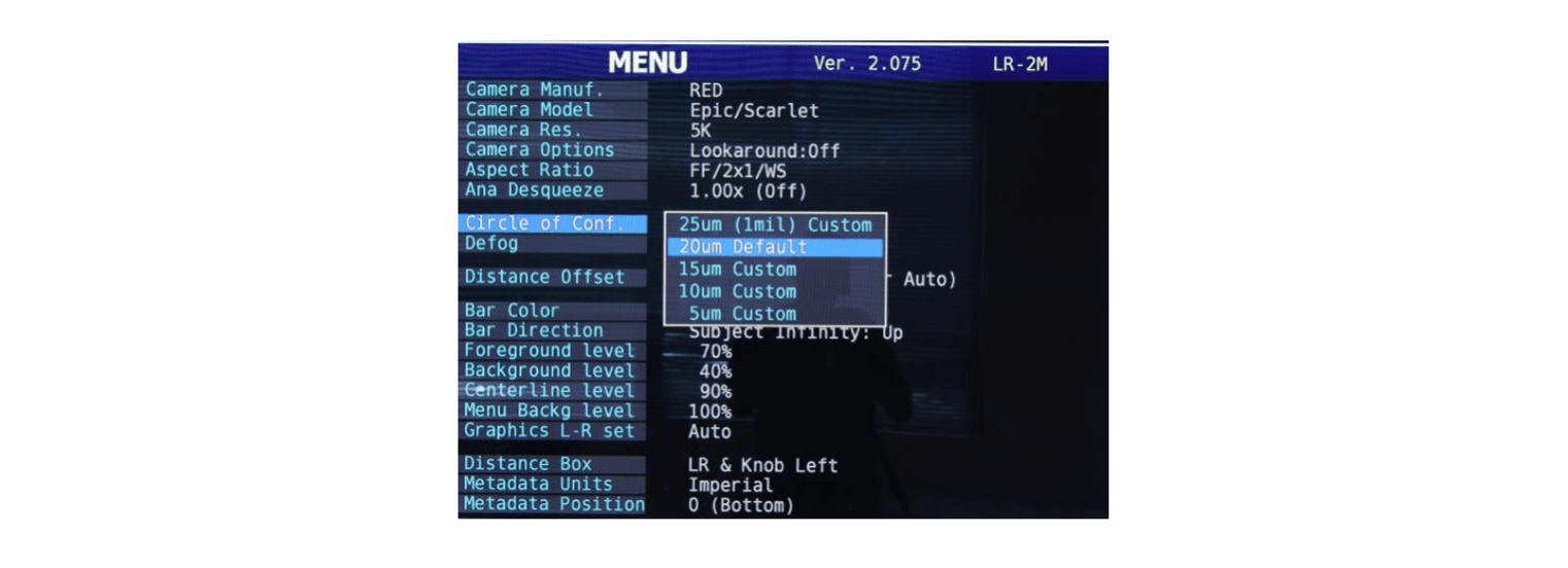
Twenty micron depth of field is the default value (approximately 0.8 mils); decreasing the value will also decrease the DOF both as it is represented by the green bars and in the metadata display.
D. The Defog setting (above) increases the usable distance in the presence of haze, fog, or smoke. The Defog algorithm removes fog-related detections close to the camera.
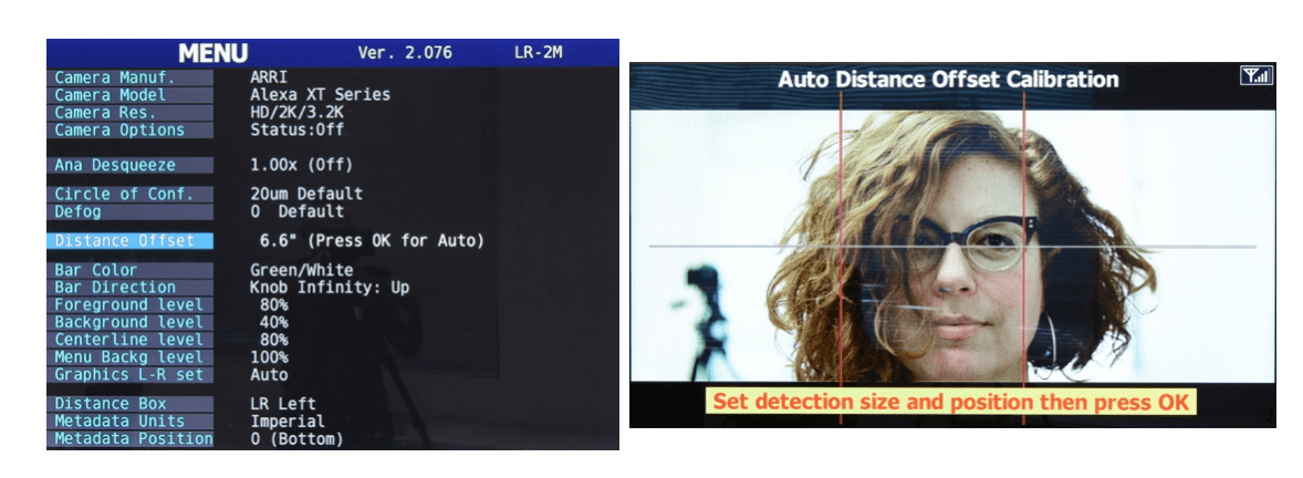
E. The Distance Offset Calibration corrects the distance measurement to the subject for the offset between the LR2 and the image plane of the camera. The offset can either be entered manually or using the Auto Offset option.
F. The color pairs in the Bar Color selection refers to the graphics indicating that the subject is within /outside the DOF. The green/white selection is shown below, right.
G. The Bar Direction selections:
H. Foreground Level, Background Level, Centerline Level and Menu Background level determine the transparency of the corresponding graphics. Adjust to taste.
I. The Graphics L-R set (below, left) determine how the graphics respond as the camera/LR2 are tilted. A rotation >90° from horizontal will flip the camera image L→R. In Auto mode the graphics don’t flip Left/Right until the tilt angle is > 135°. The graphics can also be locked in the normal left/right orientation (Fixed Up) or locked in the reversed left/right orientation (Fixed Down).
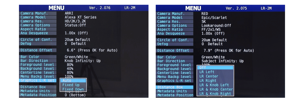
J. Distance Box (above, right) sets the position of the distance readings from the focus knob and LR2. The picture below shows LR and Knob distances in the upper left corner.
A. Choosing a Sensor.
The LR2W, LR2/ LR2M sensors are each optimized for a different range of focal length lenses. The “W” version covers a 50° horizontal angle of view and is best matched to wide-medium focal length lenses. The coverage for LR2 and LR2M is essentially equivalent 18°/20°, matching mid to long focal lengths.
The pictures below compare the overlay graphics for the LR2W and LR2/LR2M for three focal lengths 30mm, 60mm, and 90mm with a S35 format sensor.
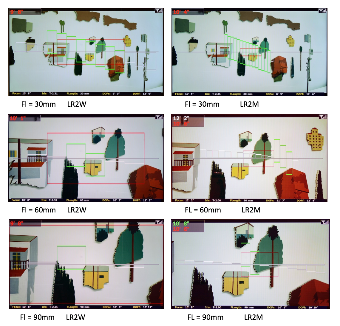
The number and sizes of the rectangles shown on the monitor depends of the horizontal angle of view of the camera and lens. When the horizontal angle of the camera is greater than the LR2 angle of view, all sixteen rectangles will be shown. Otherwise, the number of rectangles shown will be proportionately less. For FL= 90mm (above, bottom row), the LR2W shows 4 rectangles vs 16 for the LR2M. In contrast, for FL = 30mm (above, top row), the LR2W has 14 rectangles covering the entire frame, while the LR2M has its 16 rectangles only covering about half of the frame horizontally.
B. Using the monitor graphics
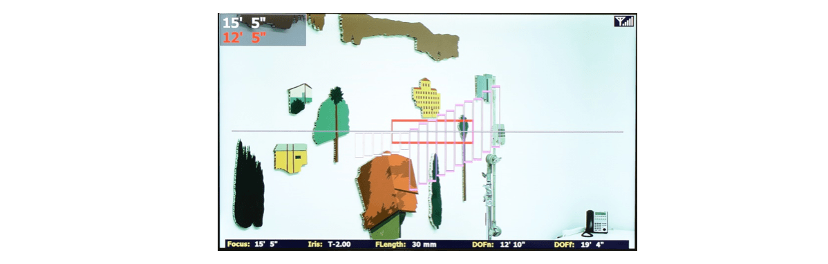
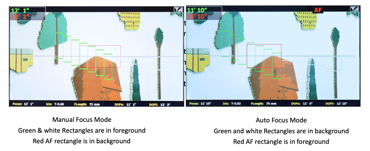
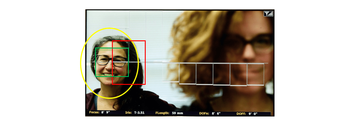
1) The sixteen rectangles arranged horizontally across the frame represent the sixteen areas where subject distances are measured. The autofocus (AF) area is made by merging two to sixteen of the rectangles and displaying the combined area by a red rectangle – the AF area. The distance displayed on the monitor Distance Box is taken from the subject within this AF Area.
The brightness of the red AF area changes depending on whether Manual or AF mode is selected. In Manual mode, the red AF rectangle is in the background where its brightness is set by the Background Level menu item.
2) The Foreground bars (below, left) show in what direction and the amount the focus knob must be turned to bring one or more of the subjects appearing on the monitor into the depth of field of the lens.
3) Use the background bars to make a smooth transition from AF mode to Manual mode. While in the AF mode, before switching to Manual mode, turn the focus knob to change the background bars beneath the red AF rectangle to green. The switch to Manual Mode will now be perfectly smooth.
C. Control the AF Zone from the Hand Unit.
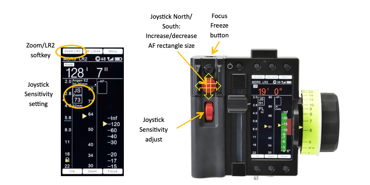
1) HU4. Set the joystick function to LR2. Both the touch area (Zoom/LR2) (picture below, left) and the switch located directly above toggle the joystick function between Zoom and LR2. Move the AF area left/right by pressing the joystick in the east/west direction; pressing the joystick north/south increases/decreases the size of the AF area (below, right).
2) HU3. Use the East/West navigation keys to shift the AF area left/right and the North/South navigation keys increase/decrease the size of the AF area. (Picture below).
D. Selecting Light Ranger Modes.
1) HU4
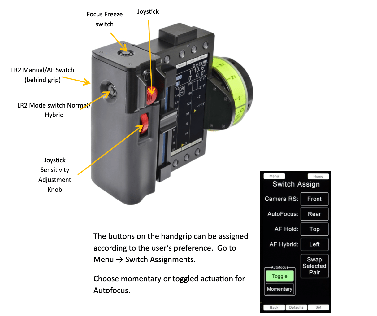
The switches and joystick integrated into the handgrip provide immediate access to LR2 functions. The switches can be reassigned from their default functions from the Switch Assign page
Manual/Autofocus switch. Default switch position: Rear Handgrip. This switch can be configured from the Switch Assign page to operate in either toggle mode or momentary mode. In Toggle mode, each switch actuation alternates between Manual mode and AF mode. In Momentary mode, the AF mode is maintained as long as the switch remains depressed.
Manual focus mode: the focus setting of the lens is controlled by the focus knob; the overlay graphics indicate whether subjects are further from or closer to the camera image plane. When the bars turn green, the subject is within the lens DOF.
Where the bars are green over the red AF rectangle, the mode can be changed from Manual to AF mode without the focus motor jumping.
Similarly, to make a smooth transition between AF to Manual modes, first turn the focus knob to bring the bars over the red AF rectangle to green, and then the transition to Manual mode will be perfectly smooth.
AF mode: the lens will focus to the nearest object within the Red AF rectangle shown on the monitor. Use the joystick to adjust the size and position of the AF rectangle to cover the subject.
The Hybrid mode combines the organic feel of a manual focus pull with the accuracy of AF. As focus is pulled from a first to a second subject, the transition to AF occurs when the focus pull brings the subject within the lens DOF. The yellow AF rectangle indicates Hybrid mode. The AF rectangle becomes red when the manual focus pull brings the subject within the lens DOF triggering the mode transition to AF.
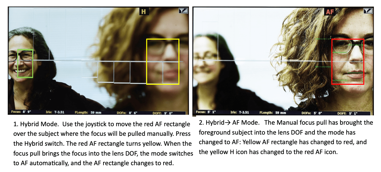
To set up a shot in Hybrid mode:
2) HU3
Manual and Autofocus mode selection.
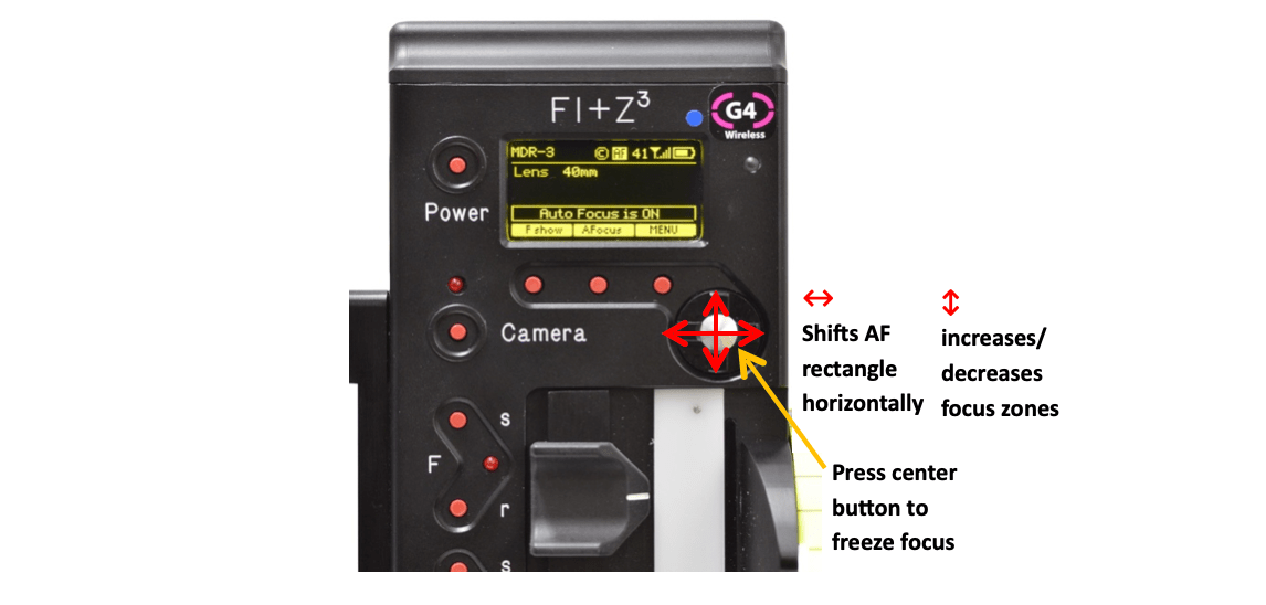
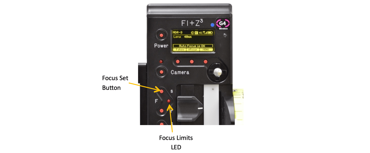
When the LR2 is present in the FI+Z system, pressing the center softkey (below, left) toggles between Manual and AF mode. The HU3 displays AF notification (below, right)
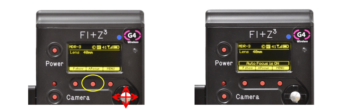
Use the East/West navigation keys (above, left) to shift the AF area left/right and the North/South navigation keys to increase/decrease the size of the AF area.
HU3, Hybrid Mode. In the HU3, there are two AF modes that are selected from the Menu: Auto/Manual and Hybrid/Manual: Menu → AF Mode → Hybr/Manual (dropdown menu).
E. Basic Ranging Mode.
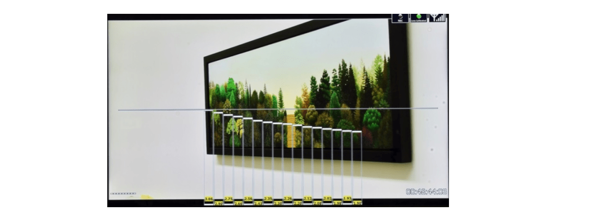
Enter the Basic Ranging Mode by pressing the OK button on the Video Interface Unit. The distances from the camera focal plane to the subject within each of the zones is displayed at the bottom of each rectangle, forming a “depth map” of the scene.
F. LR2 Focus Distance Limits
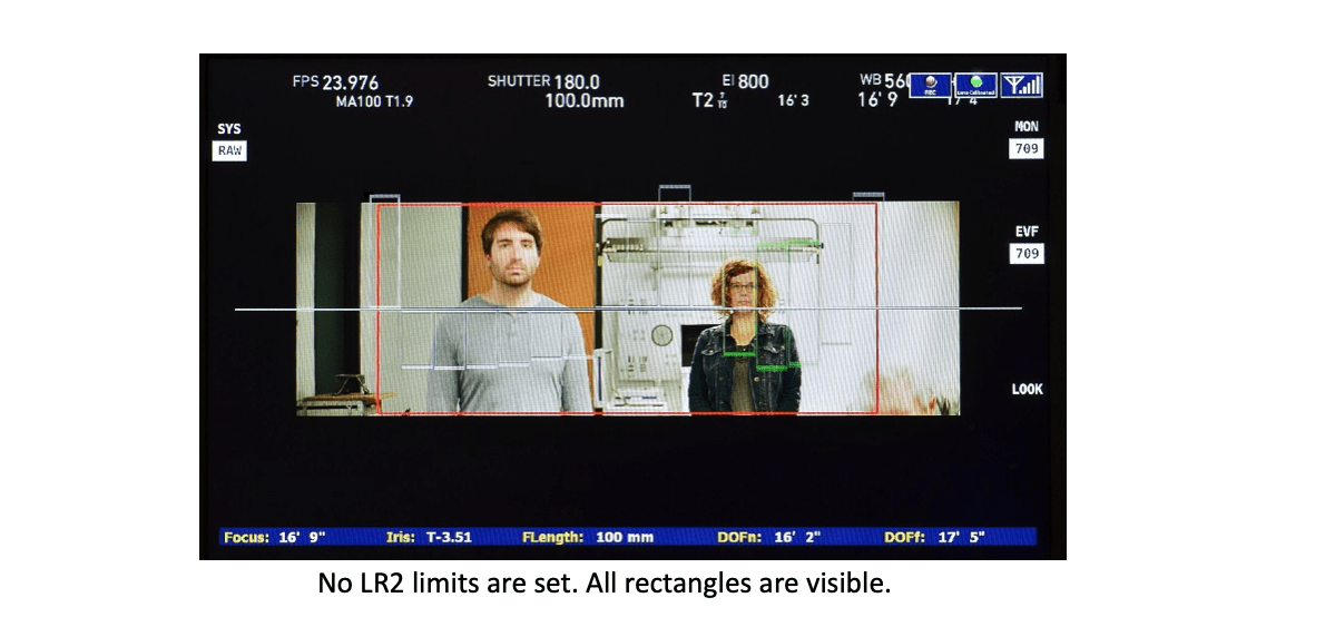
In Manual and Hybrid modes, adding LR2 limits will eliminate the display of rectangles that are outside of the LR2 limits. This will minimize graphics clutter so the user can concentrate on the subjects of interest.
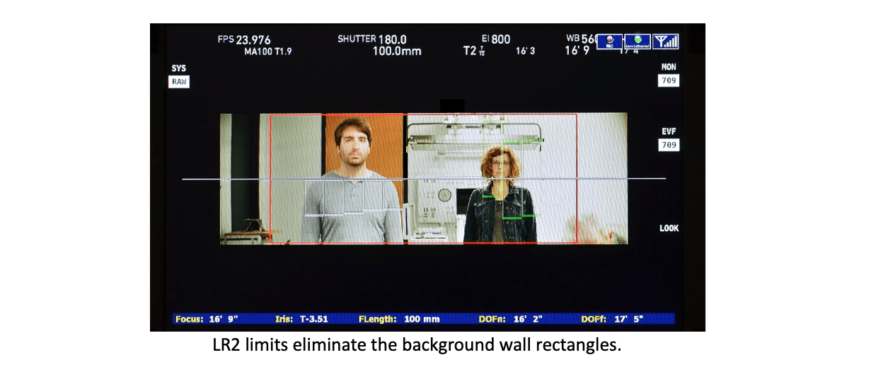
In AF mode, LR2 Limits restrict focus to subjects within the set range of limits. For example, limits can prevent the focus from jumping to a subject close to the camera entering frame as the camera is panned to follow a subject at a longer distance.
1) HU4 LR Limits
To set LR Limits with the HU4, turn the focus knob to the first distance limit, press the button above “LR2 Limits”, and rotate the focus knob to the second limit. Release the button. The LR2 Limit is shown as a red stripe to the right of the focus scale. The warning “LR Limits” appears to the left of the focus scale.
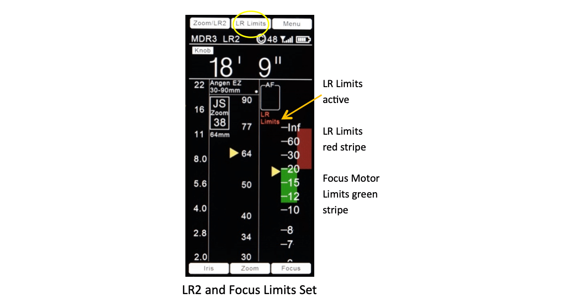
The HU4 allows separate limits to be set for the LR2 as well as the focus motor (Focus Limits). The green stripe over the focus scale shows the range of focus limits.
2) HU3 LR Limits
When the LR2 is present, the HU3 Focus Set Button only sets LR2 limits, not focus motor limits. The HU4 supports separate LR2 and Focus Motor limits.
To set LR2 limits:
The LR2W and LRMW offer complimentary horizontal angles of coverage. The “W” version covers 50° horizontally and is optimized for wide angle lenses while the “M” version covering 20° excels with mid to long focal length lenses.
The tables below show module recommendations based on lens focal lengths and camera format. Since the sensor modules have fixed horizontal angles of view, the size of the overlay graphics will vary with the camera’s angle of view. The recommended range of focal lengths for each module correspond to how fully the 16 bars of the focus assist graphics fill the monitor - from 50% of the monitor’s image width to 200% of the image width.
A. Recommended Range of Focal Lengths for LR2M, LR2W
LR2M recommended range of focal lengths
| Camera Format | Lens focal length (mm) for 16 bars occupying 100% of picture width Fig. 1 |
Recommended range of focal lengths (mm) 16 bars occupy 50% to 200% of picture width Fig. 2, 3 |
|---|---|---|
| Full Frame | 102 | 49 - 205 |
| S35 | 71 | 34 - 142 |
LR2W recommended range of focal lengths
| Camera Format | Lens focal length (mm) for 16 bars occupying 100% of picture width |
Recommended range of focal lengths (mm) 16 bars occupy 50% to 200% of picture width |
|---|---|---|
| Full Frame | 39 | 15 - 81 |
| S35 | 27 | 10 - 56 |
B. Sensor Data
| LR2 Sensors | LR2W | LR2M |
|---|---|---|
| Operating Range* (typical) | 1’ to 40’ | 1’ to 40’+ |
| Horizontal angle of view | 50° | 20° |
| Vertical angle of view | 5.1° | 3° |
| Number of detection zones | 16 | 16 |
| Detection zone width (each) | 3.1° | 1.25° |
| Emission wavelength | 905nm | 905nm |
| IEC Eye Safety | Class 1 (Eyesafe) | Class 1 (Eyesafe) |
| Size | 3.9 x 2.8 x 2.5 inches | 3.9 x 2.8 x 2.5 inches |
| Weight | 460g | 592g |
| Power** | 10-32VDC | 10-32VDC |
* Actual range depends on the size and reflectivity of the subject as well as the presence of smoke or fog; either of which will diminish the useful range.
** Power through the Serial Cable connection to the MDR or the optional cable PN4641 2-pin Lemo to D-tap. The optional cable is highly recommended as voltage fluctuations at the camera can result in intermittent operation.
C. Video Interface Unit
LR2 Video Overlay Unit with G4 wireless link
D. Brackets, Cables, and Accessories
1) Brackets
2) Typical LR2 cables and accessories
| P/N | Qty | Description | Price | Extension |
|---|---|---|---|---|
| 6015 | 1 | Cable MDR3/MDR4-LR2 | $200 | |
| 4765 | 1 | Cable Digital MF to MDR3 Analog Port | $180 | |
| 4641 | 2 | D-Tap Power | $165 | $330 |
| 4699 | 1 | Cable 3-pin Fischer (power only) | $180 | |
| 6100 | 1 | Bluetooth Module | $300 | |
| 6101 | 1 | Cable Bluetooth Module Extension | $100 |
This device complies with part 15 of the FCC Rules. Operation is subject to the following two conditions: (1) This device may not cause harmful interference, and (2) this device must accept any interference received, including interference that may cause undesired operation. This equipment has been tested and found to comply with the limits for a class B digital device, pursuant to part 15 of the FCC Rules. These limits are designed to provide reasonable protection against harmful interference in a residential installation. This equipment generates, uses, and can radiate radio frequency energy and if not installed and used in accordance with the instructions, may cause harmful interference to radio communications. However, there is no guarantee that interference will not occur in a particular installation. If this equipment does cause harmful interference to radio or television reception, which can be determined by turning the equipment off and on, the user is encouraged to try to correct the interference by one or more of the following measures:
This equipment has been verified to comply with the limits for a class B computing device, pursuant to FCC Rules. Operation with non-approved equipment is likely to result in interference to radio and TV reception. The user is cautioned that changes and modifications made to the equipment without the approval of manufacturer could void the user's authority to operate this equipment.
FCC RF EXPOSURE STATEMENT To satisfy RF exposure requirements, this device and its antenna must operate with a separation distance of at least 20 cm from all persons and must not be co-located or operating in conjunction with any other antenna or transmitter.