Preston Cinema Systems · 1659 Eleventh Street · Santa Monica, CA 90404
tel 310-453-1852 fax 310-453-5672 www.prestoncinema.com
The HU4 hand unit provides fingertip control of Light Ranger 2 (LR2) functions giving the user incredibly fast and accurate focus control. Rugged tactile switches and a two-axis joystick are integrated into the cushioned hand grip. The tactile switches control the most frequently used LR2 functions including Autofocus/Manual mode switching, Camera Record, and focus freeze. The joystick can be switched between controlling Light Ranger functions (positioning the autofocus area, changing its size), or controlling the zoom.
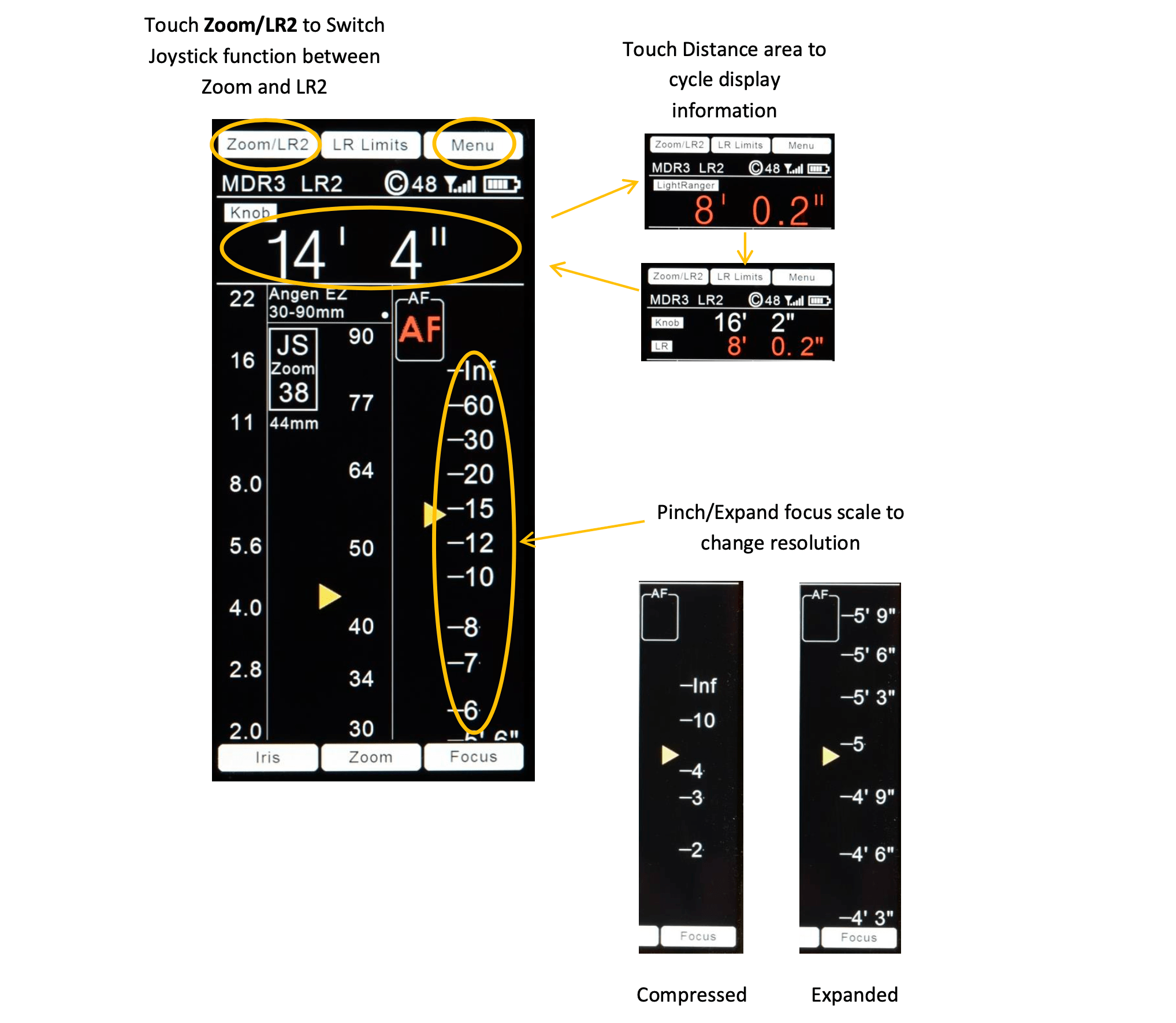
The new touch display dramatically speeds up the set-up and control of lenses. It enables the focus scale to be squeezed or expanded to decrease or increase the resolution with the touch of two fingers. Lens selection and calibration is quicker than ever. Distance data is presented with large, easy to read characters. The display’s anti-reflection coating provides excellent viewability under any lighting conditions.
Touch area short-cuts on the Home screen give quick access to the current Lens Folder and Lens Functions.
Four Lens Functions have been added (firmware ver. 1.022 and later).
Diopter focus mapping re-scales the Home screen focus scale eliminating the need to manually mark a focus ring.
The Extender/Expander compensates the displayed focal length and T-stop when an Extender/Expander is attached. It also provides correct DOF data for the LR2.
The Dolly Zoom function uses the Light Ranger 2 to keep the image size constant while the camera to subject distance changes.
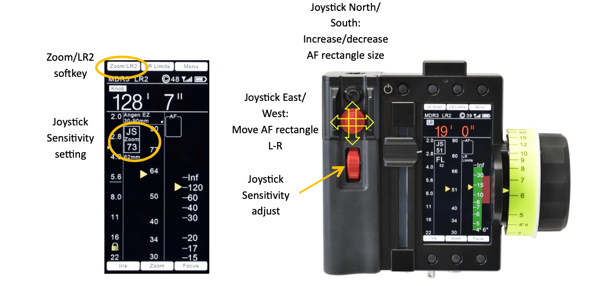
Constant Zoom speed is pre-programmed using the red knob on the HU4 handgrip. The zoom move is initiated by applying pressure to the joystick with the pre-programmed speed.
The T-stops of lenses with either linear or non-linear scales are displayed with uniform spacing making accurate setting possible throughout the range of adjustment.
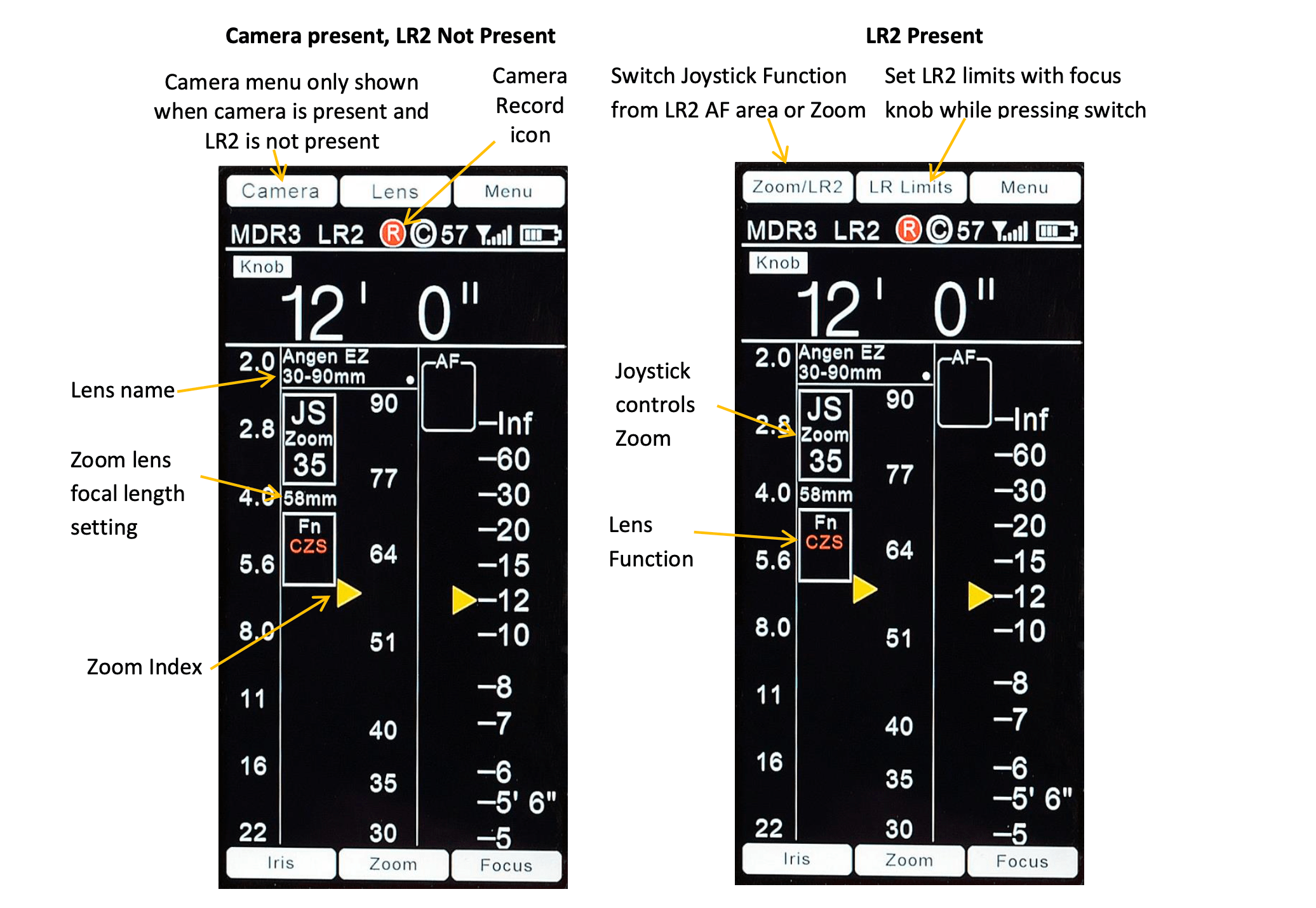
The zoom setting is displayed by an index mark that moves against the zoom scale. The numeric value of the focal length is also displayed.
Limits can be set to limit the travel of the focus, iris, and zoom rings. Separate limits can be set for the LR2 to constrain the range of distances shown by the LR2 graphics overlay as well as for autofocus. LR2 limits are used to minimize the number of graphical elements appearing on the monitor to those which are essential to the shot. They can also prevent jumps in focus when, for example, an actor crosses in front of the cameras line-of-sight.
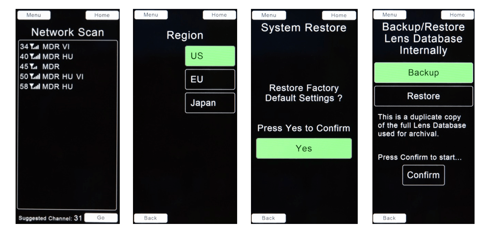
The Lens Library can now store up to 1024 lens records. The entire Library can be backed-up to the internal HU4 memory.
A motor control page (Menu → Lenses → Motors) allows setting the motor direction and torque remotely. In addition, end stop calibration for the focus, iris, and zoom motors can be initiated
Initial support for remotely controlling camera settings is provided for the RED Cameras. Support for the Sony Venice will follow as a firmware update.
The HU4 Camera Page for RED allows setting the fps, shutter angle, exposure index, and color temperature.
Red format information is automatically provided to a connected Video Overlay Unit, eliminating the need for manual entry through the Video Overlay menu. In addition, lens metadata is sent from the motor driver units for recording onto the picture file.
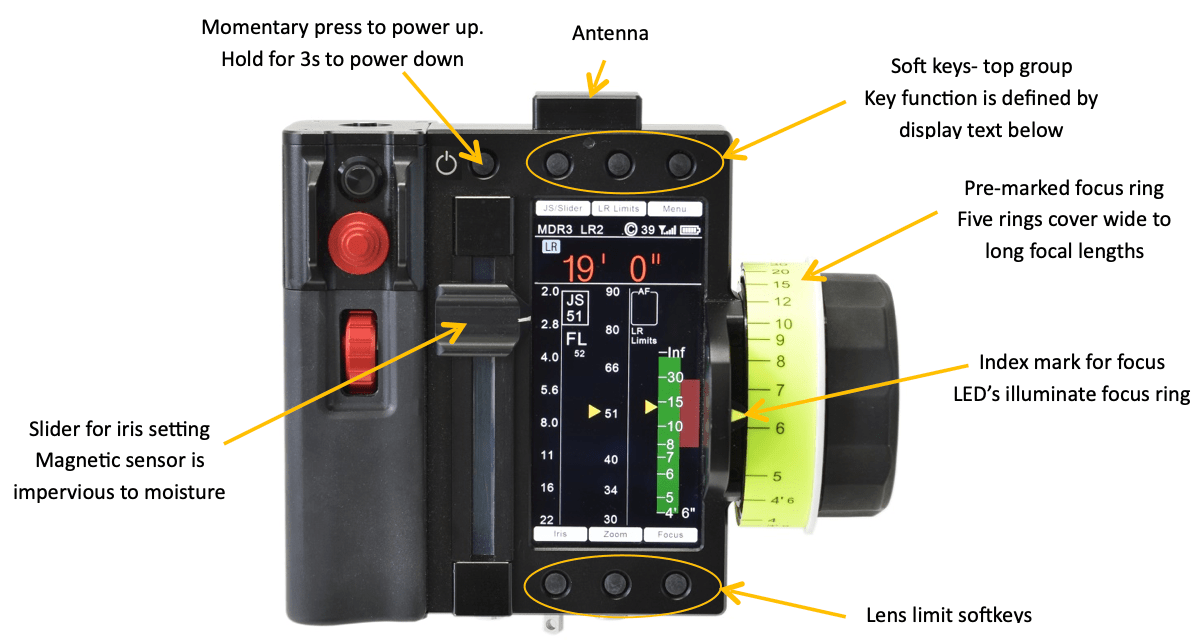
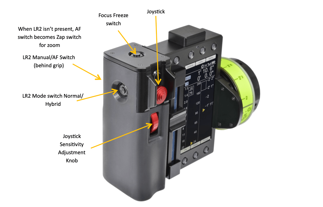
All of the controls required to operate the LR2 are located on HU4’s grip. They are:
The information shown on the display changes depending on whether the LR2 and/or a camera is connected to the MDR unit.
Lock the focus, iris, or zoom settings by momentarily touching the corresponding soft keys at the bottom of the display. The locked status is represented by a padlock icon on the respective scale.
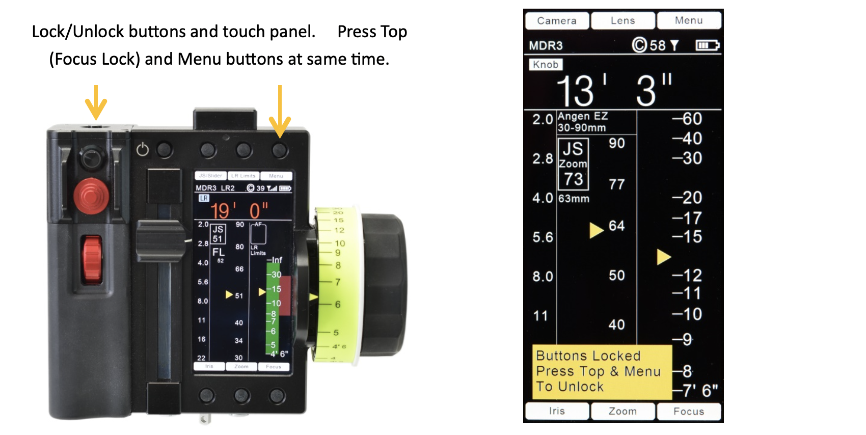
Unlock the lens setting (focus, iris, or zoom) by pressing the corresponding soft key for 1 second.
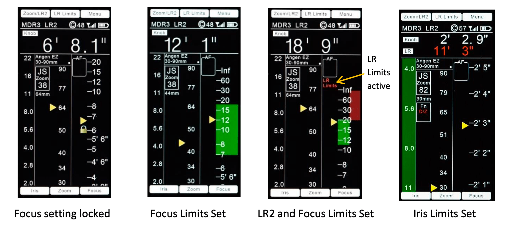
Set lens limits for the focus, iris, or zoom lens setting by pressing and holding the respective limit softkey while moving the setting of the corresponding lens ring from the beginning to the end of the desired travel. Lens limits are shown as a green strip adjacent to the corresponding lens scale.
The minimum distance difference between the beginning and end limit for focus is 0.25m (9.8”). If a smaller limit is attempted, the limit will be set to the minimum allowed.
Setting Light Ranger Distance Limits. These limits can remove graphics around areas not relevant to the scene. Set the LR2 limits by rotating the focus knob through the desired distance range while pressing the LR Limits button. Light Ranger limits are shown as a red strip adjacent to the focus scale.
Remove Lens and Light Ranger Limits by pressing the LR Limits soft key for 1 second.
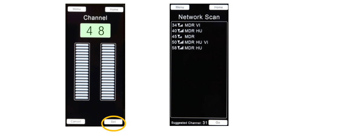
A. Wireless Channel Selection. Select the same Wireless Channel for all of the units that will be working together with the HU4: motor drivers MDR3, MDR4, Video Interface Unit and any additional hand controls; Wireless Microforce, Focus/Iris unit.
Set the Channel selection before leaving the page.
The Network Scan: Menu → System → Network displays the FI+Z units in the vicinity. A clear channel selection “Suggested Channel” is shown at the bottom of the display. Select Go to accept the channel selection. Otherwise use the scroll wheels to select an unused wireless channel.
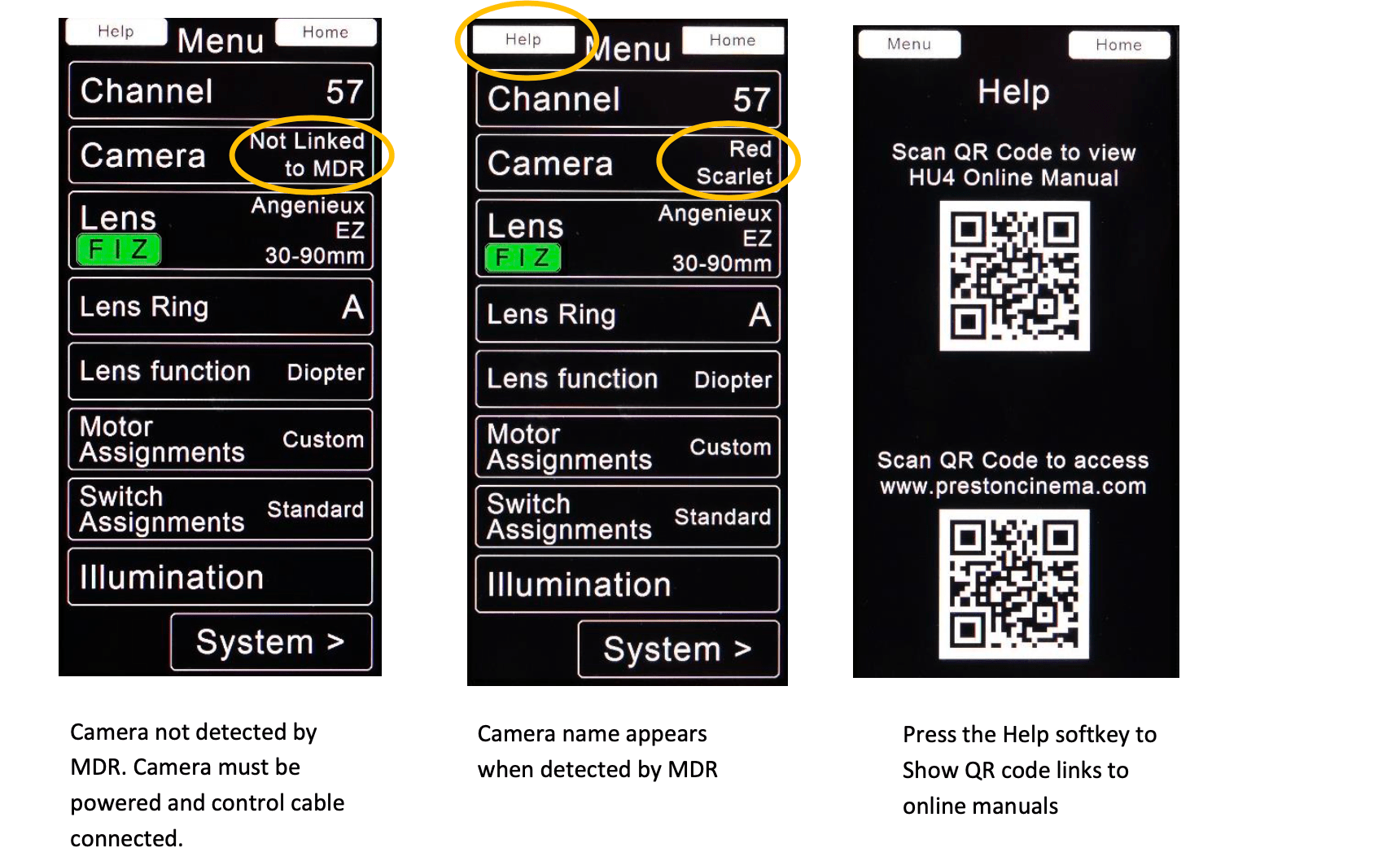
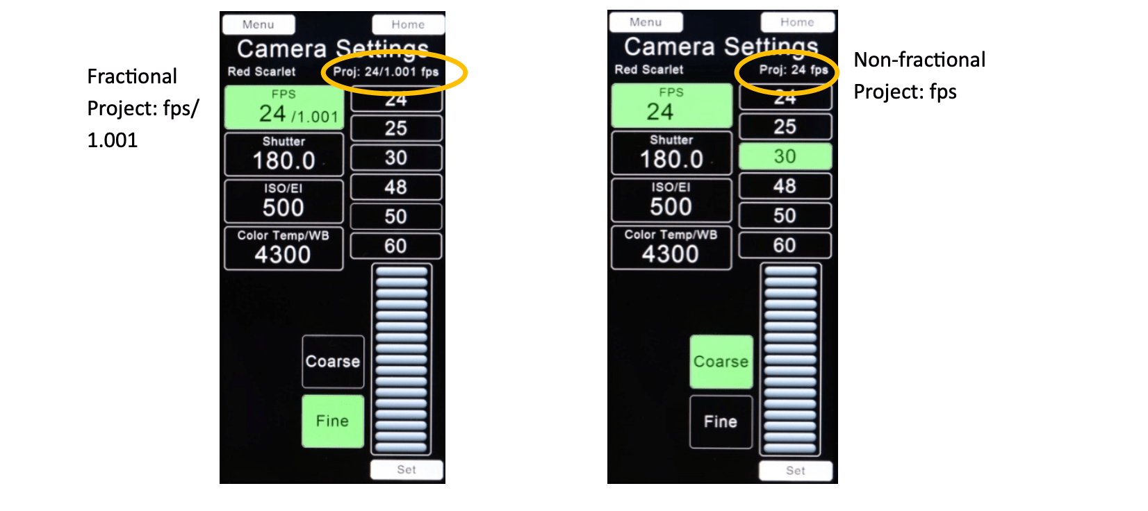
B. Camera Settings Menu → Camera are shown for supported cameras when the MDR is connected to the camera with the corresponding control cable.
When the camera project fps is fractional (fps divided by 1.001), the integral fps value is displayed with the fractional indication as shown as fps/1.001 (left, below). The display for non-fractional project fps is shown below right.
The fps can be selected either from the FPS selection box or from the list of indexed values to the right.
The shutter angle, ISO and Color Temperature are set using the scroll wheel. Press Set to accept the settings.
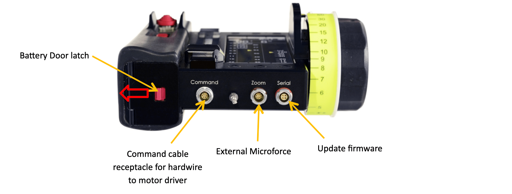
C. Lens Selection. After mounting a new lens on the camera, press the Reset button on the motor driver to calibrate the lens span. Motor calibration can also be initiated from the Motor page: Menu→ Lenses → Motors.
The Current Lens Selection is shown on the home screen and on the Lenses page: Menu → Lenses. To use this lens selection, touch the Set Lens Infinity (below, second from left), set the lens focus to infinity (below, third from left) and then touch Done.
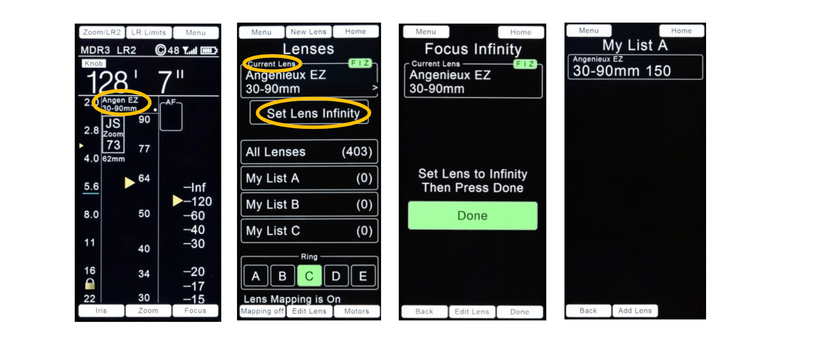
(1) To setup a lens which has already been calibrated on the camera: select a lens from the lens library: Lens → All Lenses or Menu → Lens → All Lenses. You may also choose a lens from My List A, B, or C.
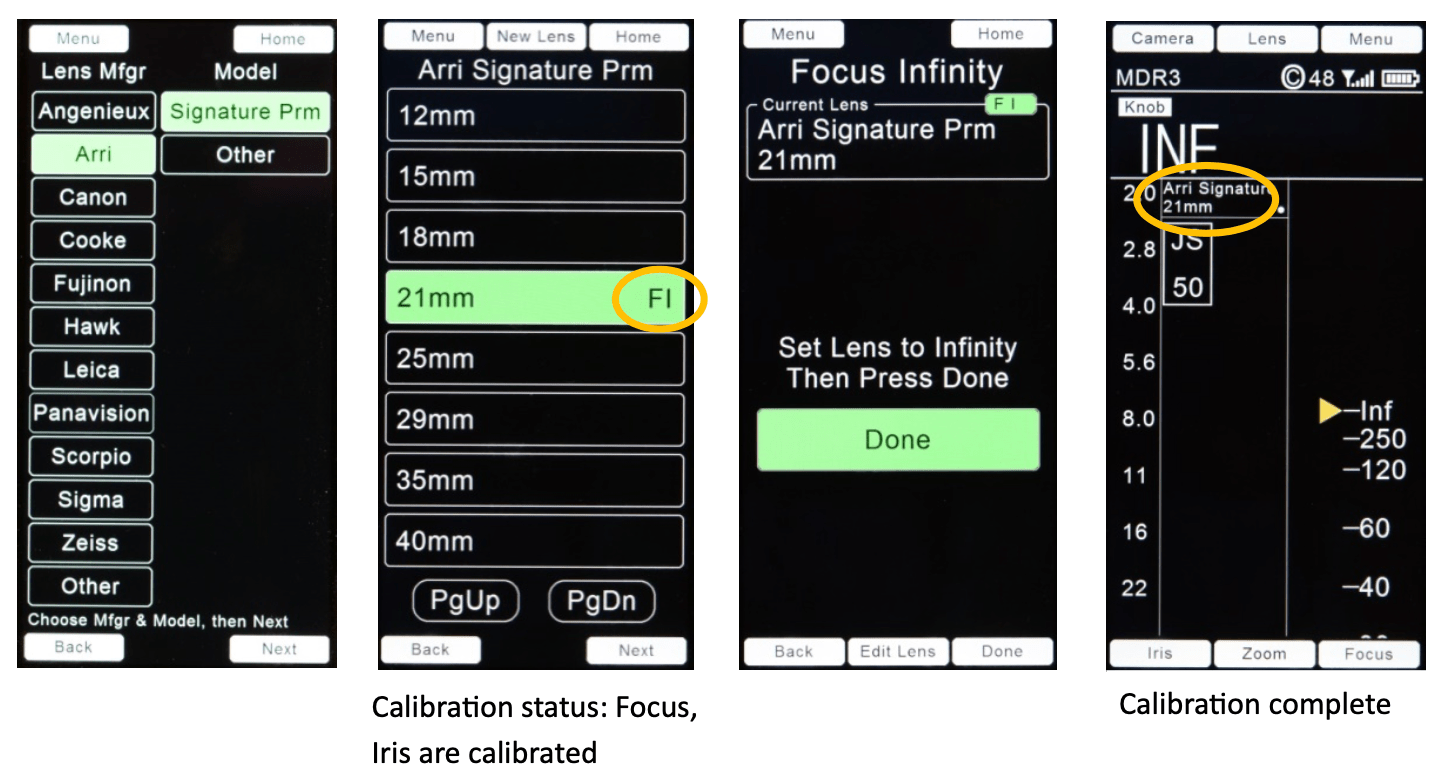
Example: select a lens from All Lenses: Choose a Manufacturer from the left column and a Model from the right column (below, left). Select Next to see the contents of the Model folder. The calibration status of each lens record is shown on the right side of the record. The selected entry is highlighted in green.
Set the lens to infinity using the focus knob to complete calibration.
(2) A New Lens can be added to the lens library either from the Lenses page (below, left) Menu → Lenses or from within the folder containing the lens models (below, second from left): Menu → Lenses → All Lenses → (Lens Mfgr) → (Model)
Starting from All Lenses, choose a Manufacturer from the left column and a Model from the right column (below, third from left). Select Next to see the contents of the Model folder. The calibration status of each lens record is shown on the right side of the record. The selected entry is highlighted in green (below, right).
Starting from within a Model folder (below, second from left), select New Lens and enter the focal length and Serial Number (below, far right).
For demonstration, we’ll create a new lens record for the 30-90mm Angenieux lens using a new serial number.
Menu → Lenses → New Lens (below, far right)
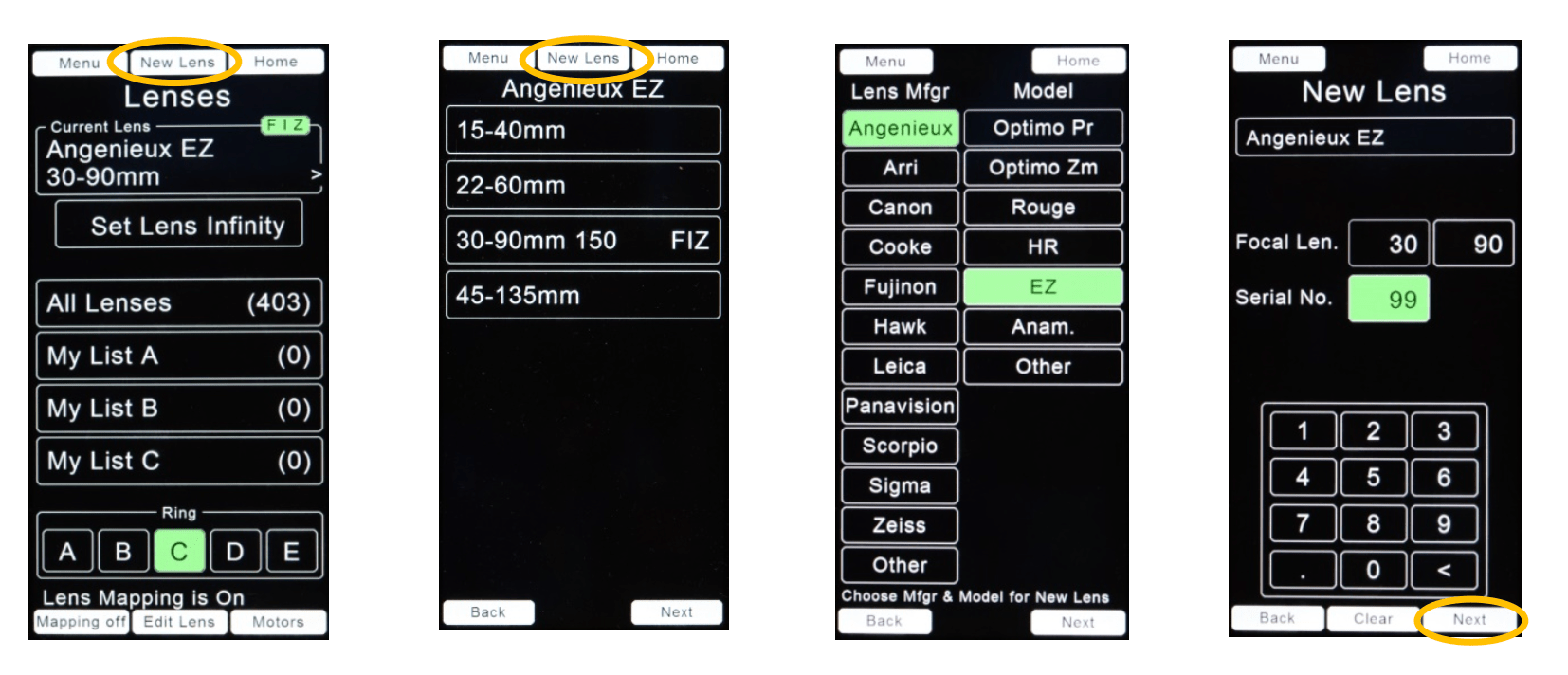
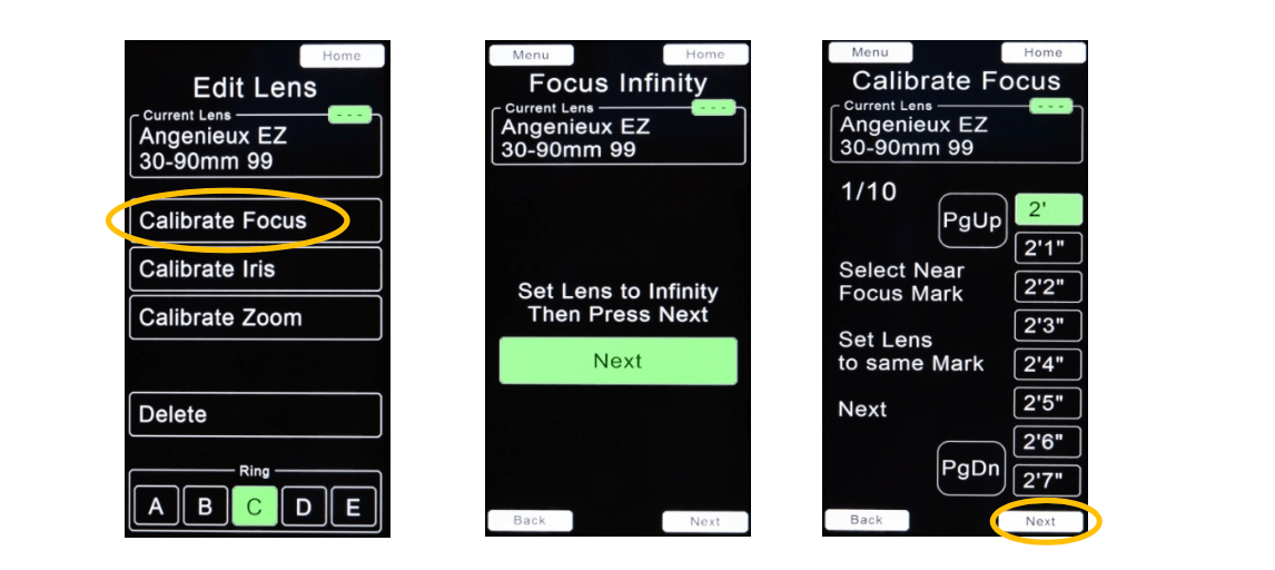
After pressing Next (above, far right), the Edit Lens page appears showing the calibration options.
(i). Lens Calibration
(a) Focus Calibration. Edit Lens → Calibrate Focus
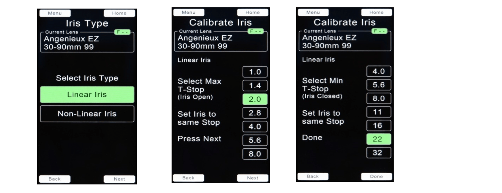
(b) Iris Calibration. Edit Lens → Calibrate Iris. The HU4 can calibrate lenses with either linear or non-linear iris scales.
To calibrate a linear iris lenses (uniform spacing between T-stops):
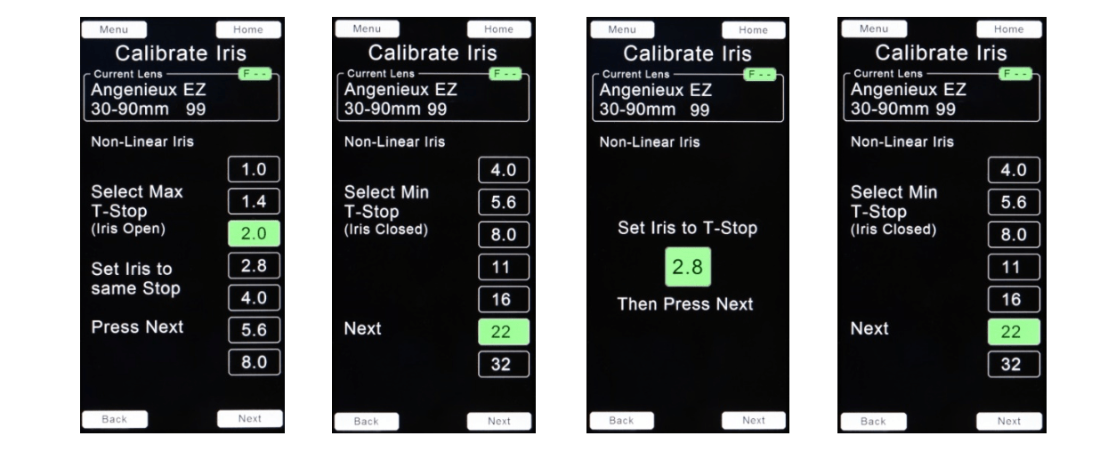
To calibrate a non-linear iris lens (non- uniform spacing between T-stops):
(c) Zoom Calibration. Edit Lens → Calibrate Zoom
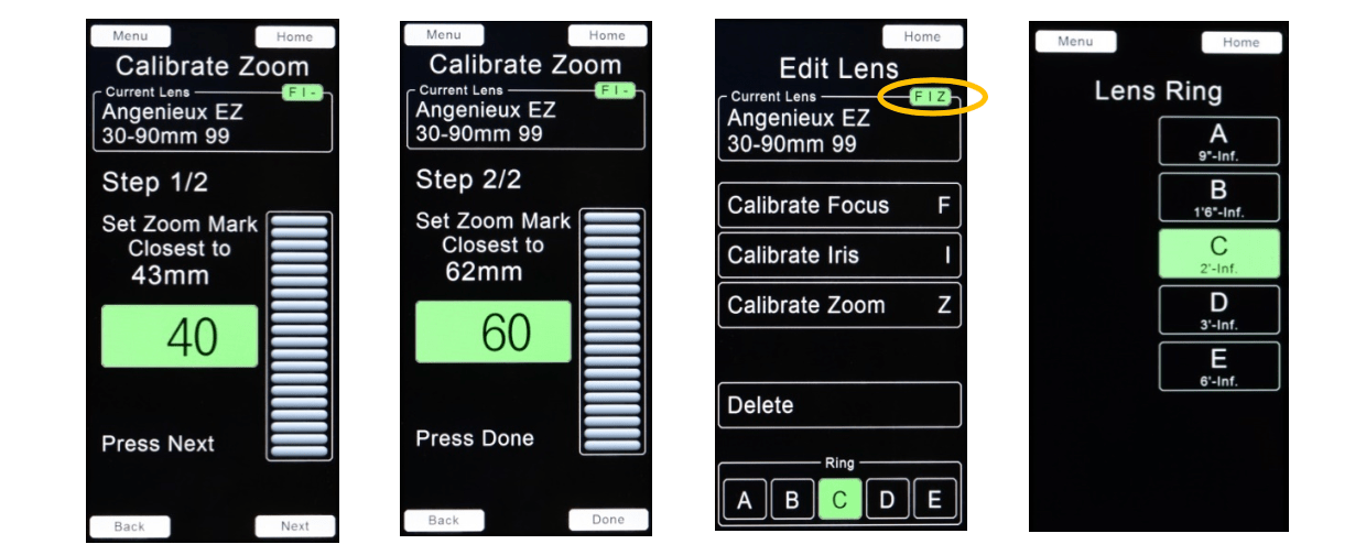
The FIZ text, highlighted in green (above, third from left) indicates that focus, iris, and zoom are calibrated.
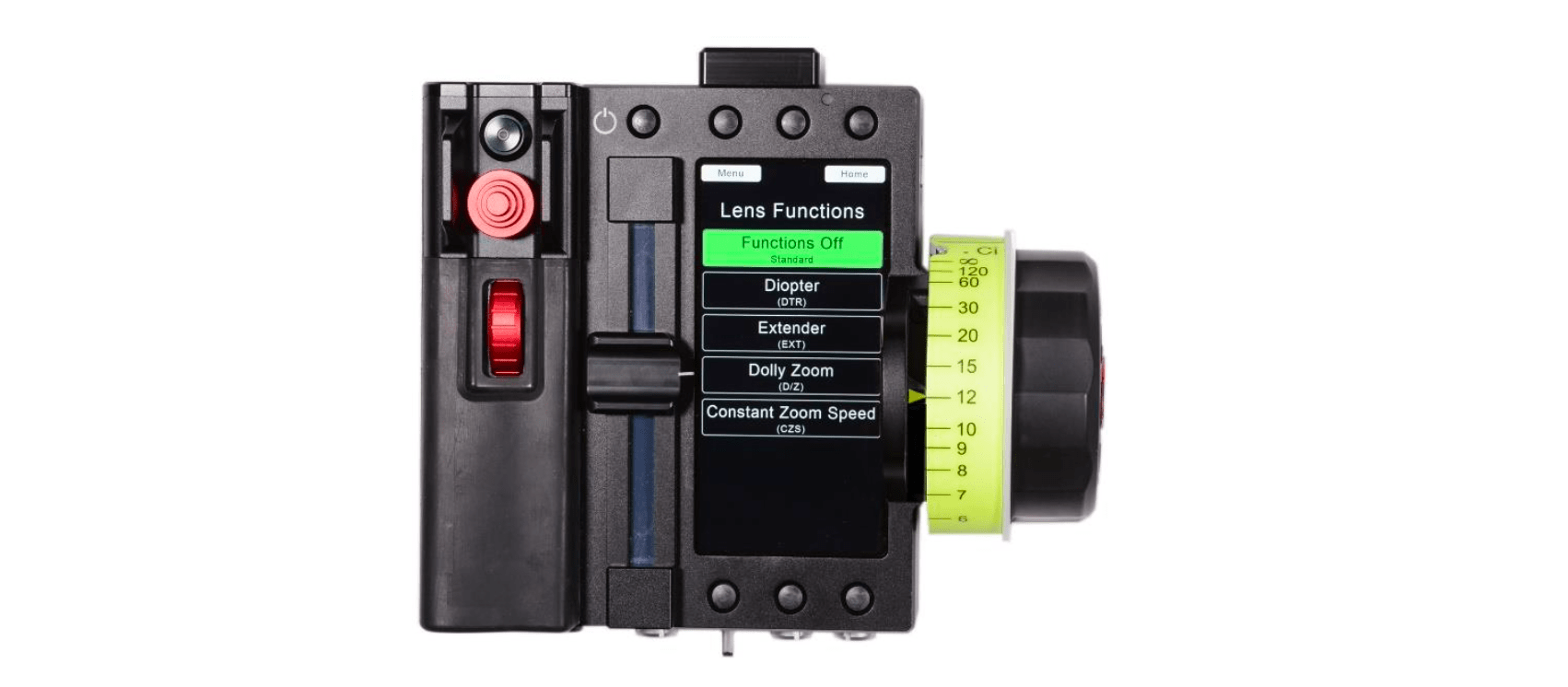
D. Lens Functions
The Lens Functions menu is accessed from the Home screen: Menu → Lens Functions or from the Lens Function touch area on the Home screen. Select the function by touching one of the rectangular virtual keys (picture below).
(i). Diopter Function (DTR). This function re-maps the focus scale on the Home screen according to the diopter power and the lens entrance pupil position. The lens entrance pupil position is determined in the diopter calibration procedure. The diopter calibration parameters are stored in the HU4 until changed by re-calibration.
MDR3 Requirements:Using the Diopter function with the Light Ranger 2 autofocus function requires a MDR3 with the current (Kinetis) processor or an MDR4. MDR3 Kinetis processor circuit boards were shipped beginning mid-2019. Please contact tech@prestoncinema.com with the MDR3 serial number and we will determine its processor version.
Before calibrating the diopter/lens combination:
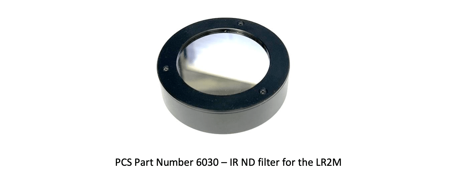
Note: ordinary neutral density camera filters meant for visible light will not work with the LR2.
Diopter calibration.This requires a focus chart, an accurate measuring tape or (preferably) a laser distance measuring device, and a stand/slider that allows accurate (millimeter accuracy) positioning of the chart relative to the camera for sharp focus.
Since calibration accuracy is crucial, we recommend that you choose Metric units (step 2, below) when entering camera image plane to focus chart distances.
(1) Attach the diopter to the lens. Navigate to the Lens Functions page and select the diopter power (below left):
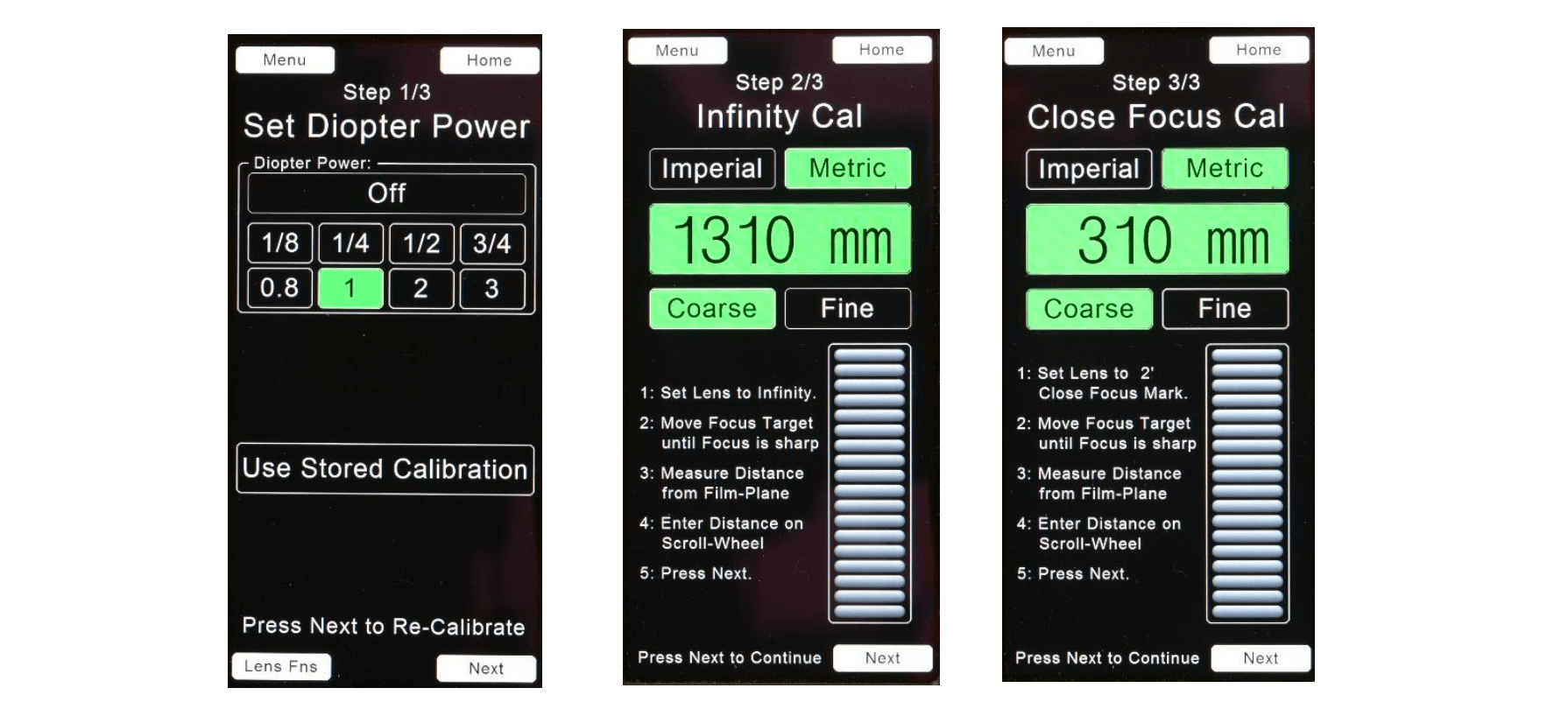
(2) Step 2/3. Set the lens focus to infinity and move the focus chart until the image is in sharp focus. Measure the distance from the focus chart to the image plane and use the scroll wheel (above, middle) to enter the distance. Since accurate calibration is essential, we recommend that the focus chart is mounted on a slider so fine adjustments can be made.
(3) Step 3/3. Set the lens to the close focus distance shown on the page (1) and move the focus chart towards the camera until it is sharp focus. Measure the distance from the focus chart to the camera image plane and enter it using the scroll wheel (above, right).
The depth of field for a combined lens/diopter set to its maximum iris opening may be as small as a few millimeters!
Steps to minimize errors when using the LR2 with the Diopter Function:
(ii) The Extender Lens Function (EXT) compensates the displayed focal length and T-stop when an extender/expander is attached to the lens.

Enter the Extender Power using the scroll wheel on the HU4 display. The range of power is from 0.5 ~2.0.
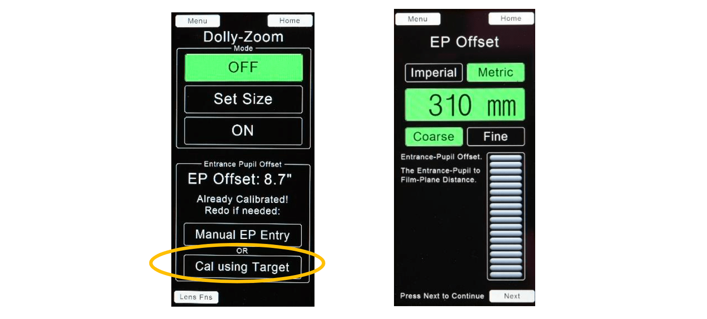
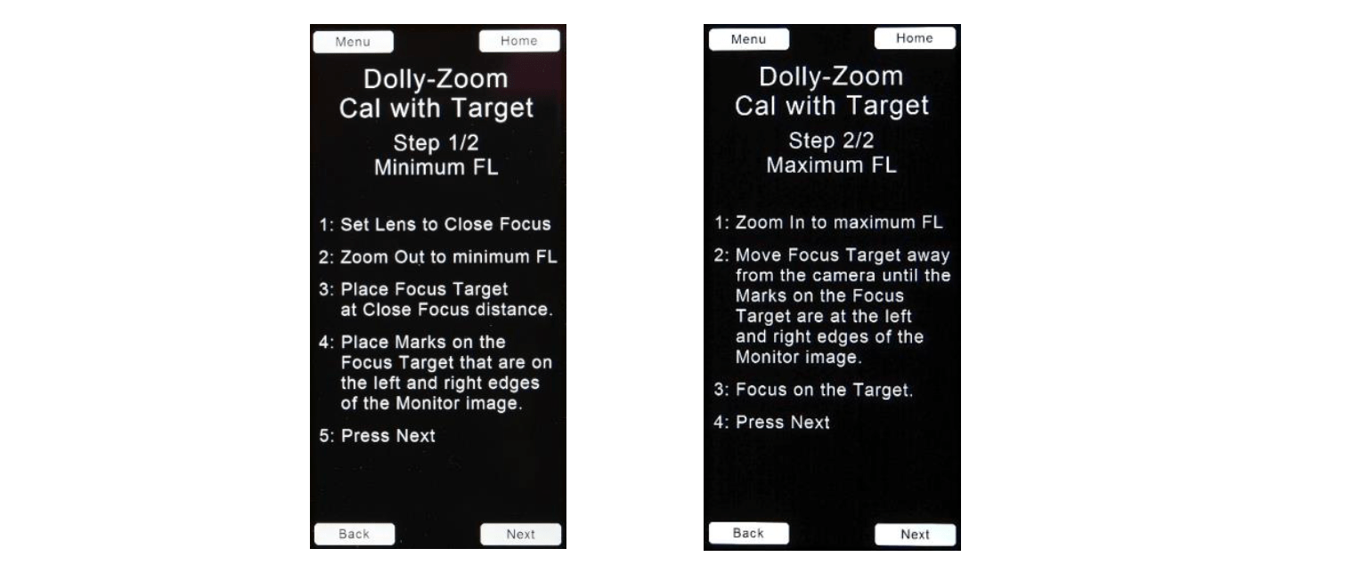
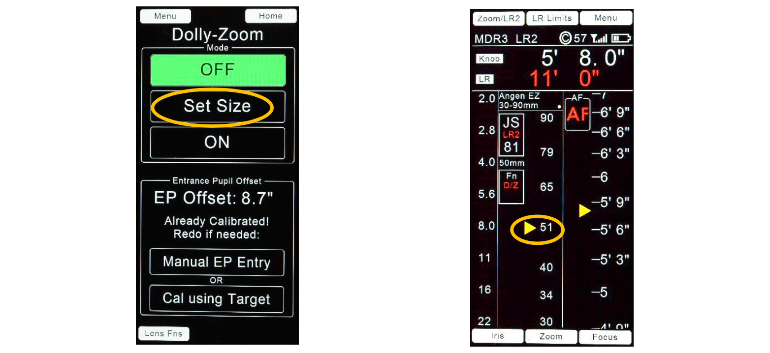
(iii) The Dolly Zoom function (ZD) keeps the image size constant while the camera to subject distance changes. This is accomplished by linking the zoom focal length to the subject to camera distance as measured by the LR2.
Procedure
(iv) Constant zoom Speed (CZS)

The desired zoom speed is set using the red knob on the grip. The zoom is started or stopped by pressing the joystick either momentarily (Momentary mode) or continuously (Continuous mode).
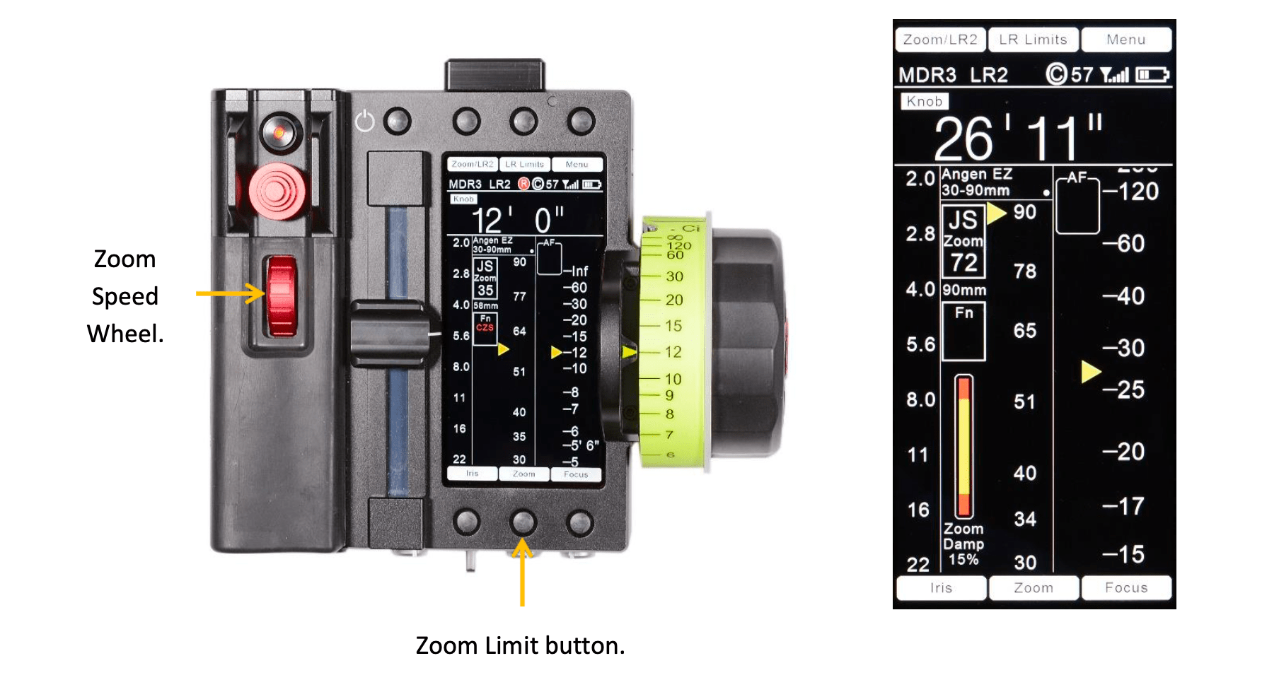
E. Zoom Soft-Stop. The soft stop function decelerates the zoom speed a programmable distance from either end of the zoom travel distance.
To program the distance from where the zoom soft-stop begins:
While pressing the Zoom limit button, turn the red zoom speed wheel in the handgrip. The distance where the soft-stop occurs is shown both in the graphic as a red area in the bar display and as a percentage of the travel of the zoom lens ring.
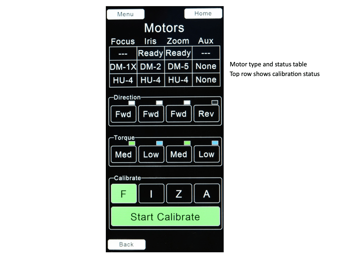
F. The Motors setup page Menu →LENSES → Motors, shows the current motor types connected to the motor driver as well as the direction and torque setting for each motor.
The direction of each motor is changed (Fwd/Rev) by touching the corresponding direction button on the display.
the Torque setting buttons cycles the torque setting: Low, Med, High for the motor in the corresponding column. The color of the rectangle in the upper right corner of each button indicates the setting: Blue, Green, Red.
Touching the F, I, Z, A buttons in the Calibrate area selects the motor or motors to be calibrated.
Touch Start Calibrate to start the motor finding the end stops of the selected lens rings.
G. Control Assignments: Menu → Control Assignments
The HU4 has three Controls for user input: Knob, Joystick, and Slider. To change one or more motor assignments:
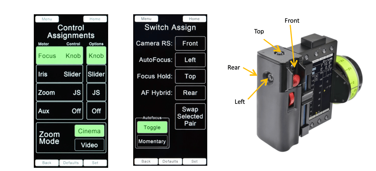
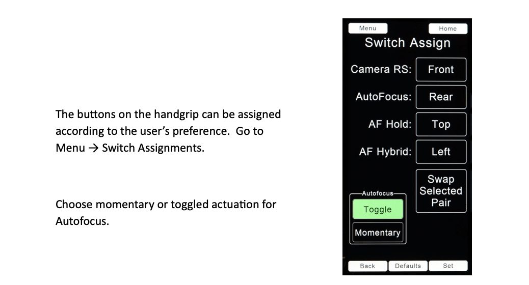
H. Switch Assignments Menu → Switch Assignments
The switches assigned to the four functions: Camera RS, AutoFocus, Focus Hold, and AF Hybrid can be re-assigned:
The switch controlling Autofocus can be set to either Toggle or Momentary by touching the corresponding button and then Set.
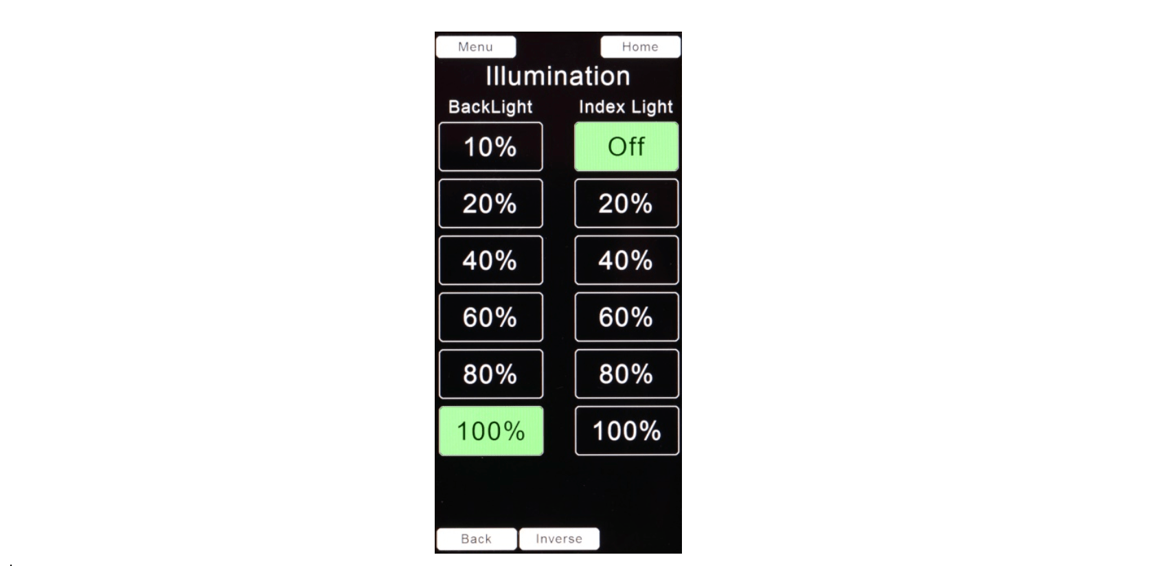
I. Illumination Control: Menu → Illumination
Change the illumination settings by touching the desired brightness level button.
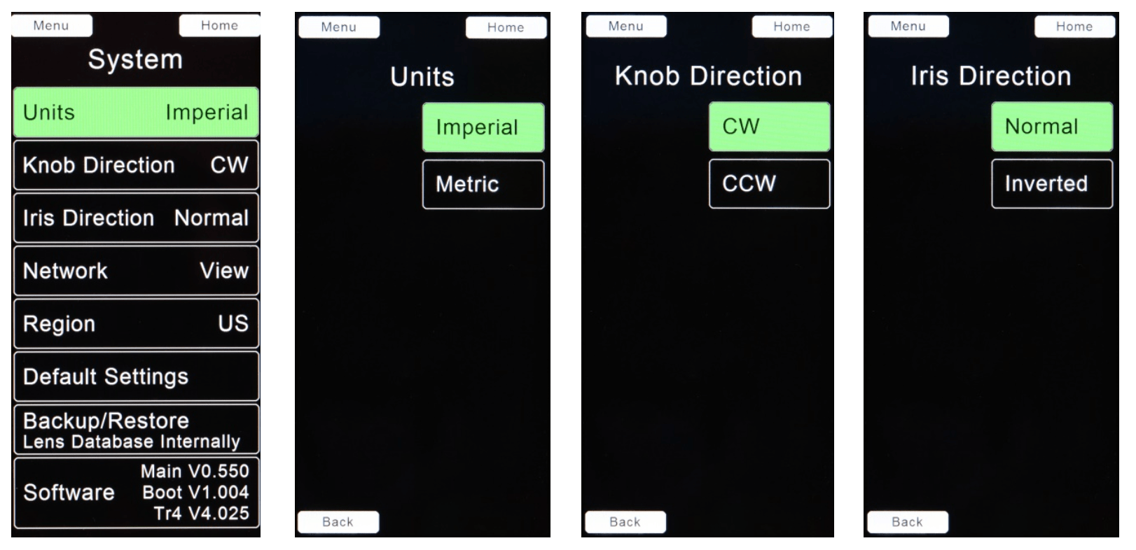
J. System Menu → System
The System menu options are self-explanatory and are shown below.
The switches and joystick integrated into the handgrip provide immediate access to LR2 functions. The switches can be reassigned from their default functions from the Switch Assign page
3.1 Manual/Autofocus switch. Default switch position: Rear Handgrip.
This switch can be configured from the Switch Assign page to operate in either toggle mode or momentary mode. In Toggle mode, each switch actuation alternates between Manual mode and AF mode. In Momentary mode, the AF mode is maintained as long as the switch remains depressed.
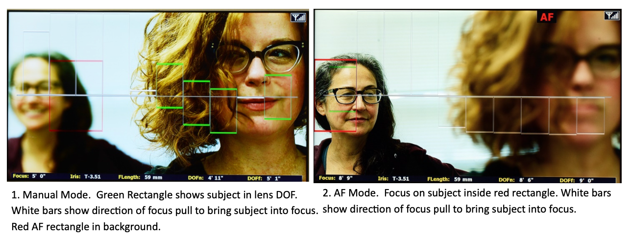
In Manual focus mode, the focus setting of the lens is controlled by the focus knob;
in AF mode, the lens will be focused to the nearest object within the Red AF rectangle shown on the monitor.
When the LR2 is not present in the system, the Manual/AF switch functions as a Zap switch for the zoom; pressing the switch sets the zoom sensitivity to maximum.
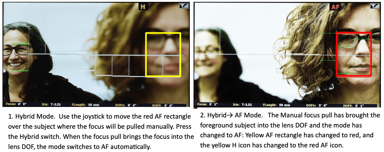
3.2 Hybrid Mode Switch. Default switch position: Left Handgrip.
The Hybrid mode combines the organic feel of a manual focus pull with the accuracy of AF. As focus is pulled from a first to a second subject, the transition to AF is seamless as it occurs when the focus pull brings the subject within the lens DOF.
To set up a shot in Hybrid mode:
3.3 Focus Freeze. Default switch position: top Handgrip.
Press this switch to freeze the focus setting. This can be used in AF mode to prevent the focus from jumping from the current subject to one crossing into the AF detection zone (red rectangle).
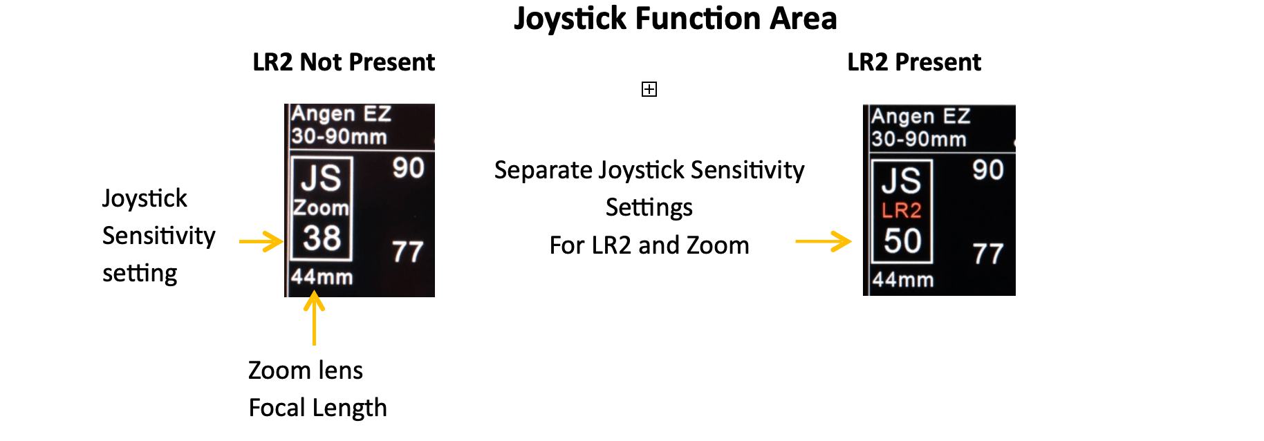
3.4 The function of the joystickcan be switched between controlling the AF frame size/position and controlling the lens zoom function. Touch the Zoom/LR2 softkey on the Home screen to switch joystick function.
Product Number: 7000
Power: Internal Battery Sony NP-FZ-100
*Because of shipping regulations, the Sony NP-FZ-100 and BC-QZ1 charger are not included.
Weight (with battery): 1.1kg (2.4 Lbs.)
Included: 1 x Set of Lens Rings Ai - Ei
Dimensions
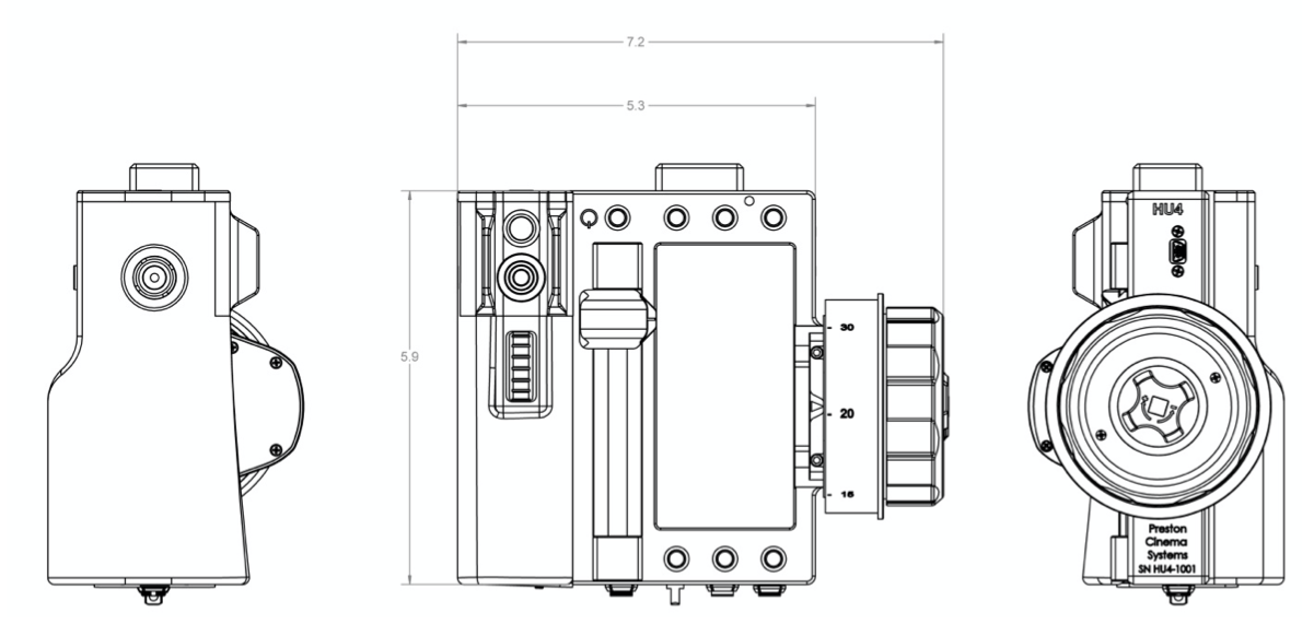
This device complies with part 15 of the FCC Rules. Operation is subject to the following two conditions: (1) This device may not cause harmful interference, and (2) this device must accept any interference received, including interference that may cause undesired operation. This equipment has been tested and found to comply with the limits for a class B digital device, pursuant to part 15 of the FCC Rules. These limits are designed to provide reasonable protection against harmful interference in a residential installation. This equipment generates, uses, and can radiate radio frequency energy and if not installed and used in accordance with the instructions, may cause harmful interference to radio communications. However, there is no guarantee that interference will not occur in a particular installation. If this equipment does cause harmful interference to radio or television reception, which can be determined by turning the equipment off and on, the user is encouraged to try to correct the interference by one or more of the following measures:
This equipment has been verified to comply with the limits for a class B computing device, pursuant to FCC Rules. Operation with non-approved equipment is likely to result in interference to radio and TV reception. The user is cautioned that changes and modifications made to the equipment without the approval of manufacturer could void the user's authority to operate this equipment.
FCC RF EXPOSURE STATEMENT To satisfy RF exposure requirements, this device and its antenna must operate with a separation distance of at least 20 cm from all persons and must not be co-located or operating in conjunction with any other antenna or transmitter.
Channels 30 – 59 are recommended, as their advanced data encoding minimizes the possibility of interference.
| Channel | MHz | Channel | MHz | Channel | MHz | ||
|---|---|---|---|---|---|---|---|
| 0/30 | 2402 | 10/40 | 2424 | 20/50 | 2458 | ||
| 1/31 | 2404 | 11/41 | 2428 | 21/51 | 2460 | ||
| 2/32 | 2406 | 12/42 | 2432 | 22/52 | 2462 | ||
| 3/33 | 2408 | 13/43 | 2436 | 23/53 | 2464 | ||
| 4/34 | 2410 | 14/44 | 2440 | 24/54 | 2466 | ||
| 5/35 | 2412 | 15/45 | 2444 | 25/55 | 24/68 | ||
| 6/36 | 2414 | 16/46 | 2448 | 26/56 | 2470 | ||
| 7/37 | 2416 | 17/47 | 2452 | 25/57 | 2472 | ||
| 8/38 | 2418 | 18/48 | 2454 | 28/58 | 2474 | ||
| 9/39 | 2420 | 19/49 | 2456 | 29/59 | 2476 |
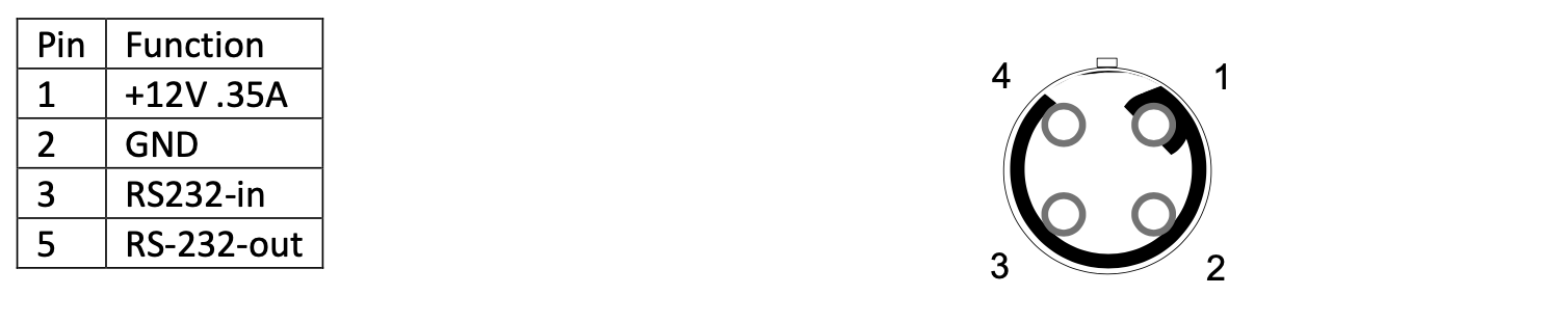
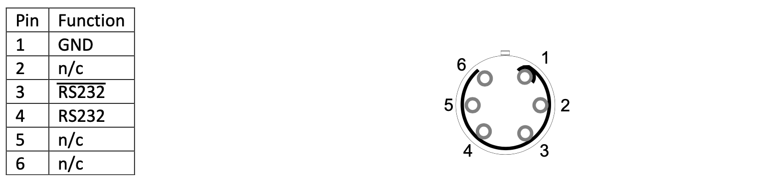
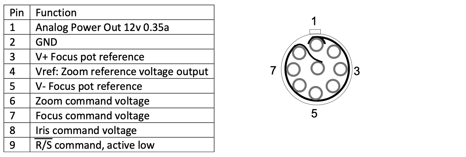
The drawings show the receptacles as viewed from the solder side.
1. HU4 Command Receptacle EGG.0B.306.CLL
2. HU4 Zoom Receptacle EGG.0B.309.CLL
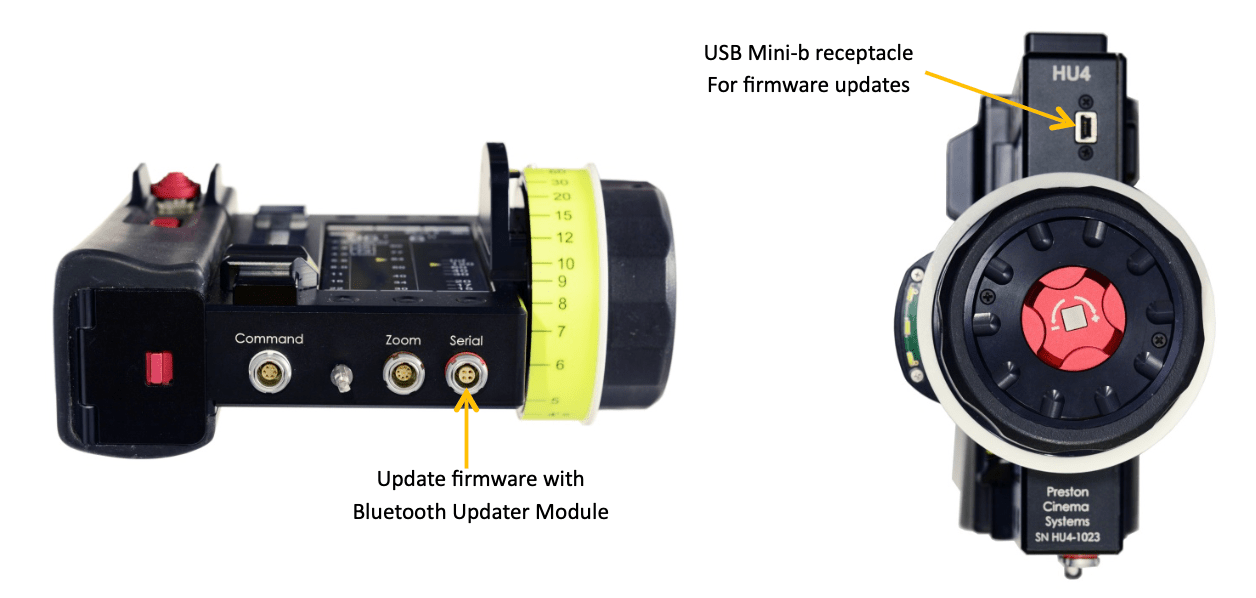
3. HU4 Serial Receptacle EGG.0B.304.CLL